10
5.52.420.00.01.07
5 Technical data
Capacity Type kg 125 250 250 500 1000 1000 2000
Chain falls 1 1 1 1 2 1 2
Duty classification
FEM 9.511/ISO 4301
2m/M5 1Am/M4 1Am/M4 1Am/M4 1Am/M4 1Bm/M3 1Am/M4
Chain dimensions mm 5x15 5x15 5x15 5x15 5x15 7x21 7x21
Lifting speed m/min 8/2 8/2 16/4 8/2 4/1 10/2,5 5/1,25
Motor power kW 0,18/0,05 0,36/0,09 0,75/0,18 0,75/0,18 0,75/0,18 1,9/0,45 1,9/0,45
Operating time ED % 100 60 100 40 40 30 30
Starting current A 2,5/0,64 4,7/1,15 9/1,7 9/1,7 9/1,7 21/4,5 21/4,5
Nominal current A 0,6/0,36 1,1/0,6 2,1/0,95 2,1/0,95 2,1/0,95 4,5/2,3 4,5/2,3
Starting - Cos f
0,88/0,8 0,88/0,8 0,88/0,8 0,88/0,8 0,88/0,8 0,88/0,8 0,88/0,8
Noise emission* db(A) 72 72 72 72 72 78 78
Weight **
S kg 30 30 33 33 33 54 54
R kg 37 37 40 40 47 68 75
H kg 44 44 47 47 54 75 93
E kg 62 62 65 65 65 83 103
Weight per m add. lift kg 0,54 0,54 0,54 0,54 1,08 1,1 2,2
Hand chain pull ~ H N 30 40 40 40 80 80 125
Travel speed E m/min 16/4 16/4 16/4 16/4 16/4 16/4 16/4
Travel motor power E kW 0,25/0,06 0,25/0,06 0,25/0,06 0,25/0,06 0,25/0,06 0,25/0,06 0,25/0,06
Travel speed E m/min 30/7,5 30/7,5 30/7,5 30/7,5 30/7,5 30/7,5 30/7,5
Travel motor power E kW 0,5/0,12 0,5/0,12 0,5/0,12 0,5/0,12 0,5/0,12 0,5/0,12 0,5/0,12
Wheel pressure max. *** kN 0,8 1,4 2,6 2,6 3,4 5,1 6,8
Beam flange width 1N
R mm 64-152 64-152 64-152 64-152 64-190 64-190 88-190
H+E mm 50-179 50-179 50-179 50-179 50-179 50-179 66-185
Beam flange width 2N
R mm 153-310 153-310 153-310 153-310 191-310 191-310 191-310
H+E mm 180-310 180-310 180-310 180-310 180-310 180-310 186-310
*) 1m distance, tolerance +2dB(A) **)at 3m suspension or track height ***) Wheel pressure including the weight of hoist device and trolley at nominal load at 3m suspension height.
Chains acc. special quality acc. Thechical requirements as EN818-7-T
3-phase current motor 400V/50Hz - IP55 – F – max. 1000 m above sea level.
Order-related Special data, refer to the motor nameplate.
6 Installation
6.1 Stationary hoist
Stationary designs are supplied with a suspension eye. A suspension hook is available as option.
They are usually supplied assembled in full. In exceptional circumstances, the suspension eye/ suspension
hook is not assembled.
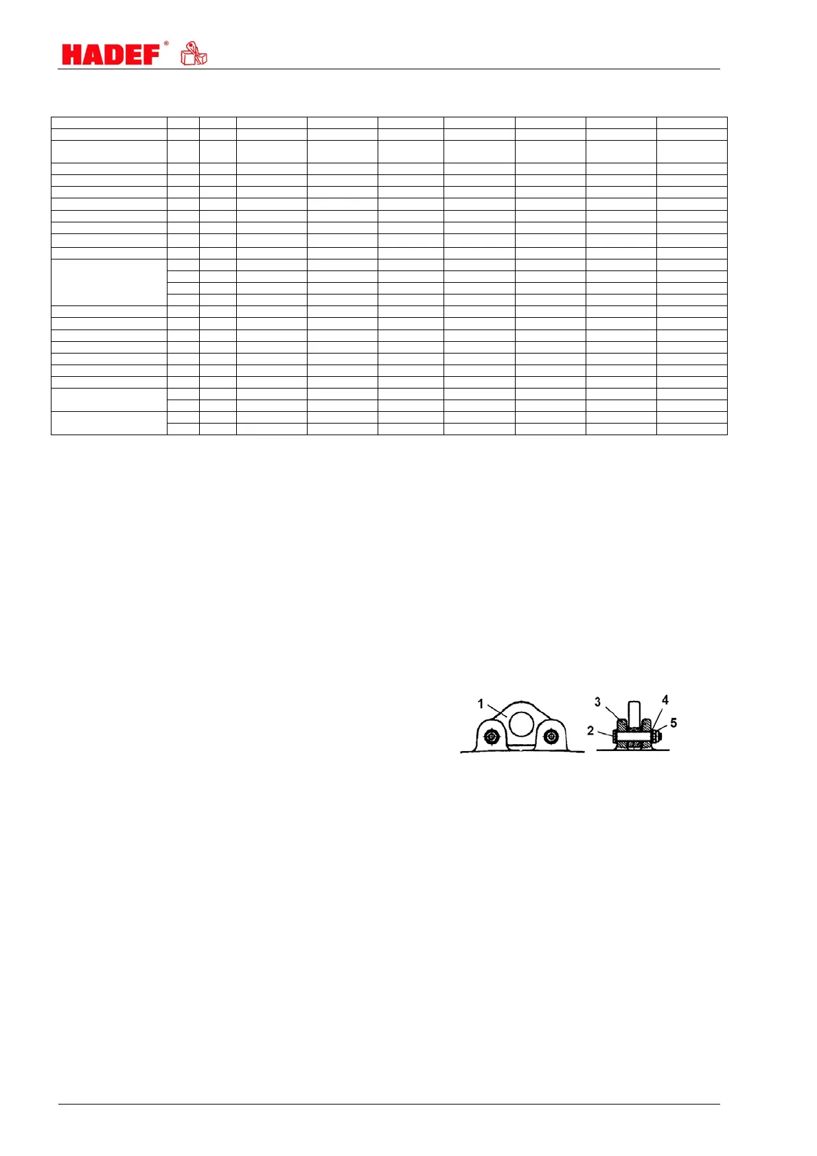
Suspension eye and suspension hook
fix the suspension eye (1) by two threated bolts
(2) at the provided fishplates (3) on top of the
hoist housing
put on disc (4)
fix nuts M10-10.9 (5) with tightening torque 49
Nm
additionally protect the nuts with LOCTITE 243
Illustration 2
Suspension hook installation in the same way.
6.2 Adjusting the gauge
The trolley can be adjusted to various beam flange widths. Adjustment to the relevant beam flange width “B”
depends on the type and size and is to be made as follows: