16
5.52.420.00.01.07
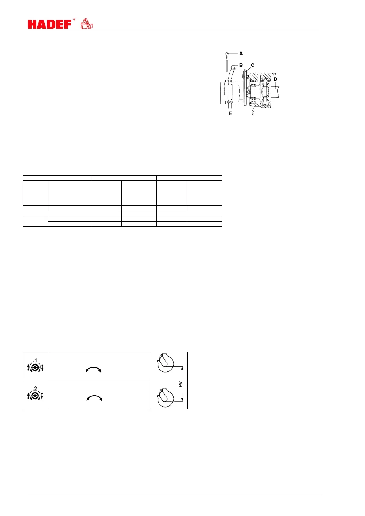
9.5 Adjustment - limit switch for lifting
If desired the chain hoist can be fitted with a limit
switch for lifting GTES 51-67 or GTES 51-180.
It allows to adjust any switching point desired, for
example the limit positions of upper and lower
hook position. The slipping clutch incorporated in
the hoist serves as emergency stop.
If the chain hoist is supplied with switch included,
a switching point for upper and lower hook
position is preset.
The setting can be adjusted at the set screws 1
and 2 with a screw driver ø 4mm or 4mm
hexagon socket screw key. The table shows the
hook path for one turn of the set screw.
A Adjustment with screw driver ø 4mm
B set screw
C Adapter
D Chain sprocket shaft
E Control cams
125 kg/1 up to 1000 kg/2 1000 kg/1 and 2000 kg/2
chain falls type of limit switch for
lifting
hook path hook path per
turn of set screw
1 and 2
mm
hook path
hook path per
turn of set screw
1 and 2
mm
1 GTES 51 - 67 <=9m 92 <=12m 130
GTES 51 - 180 >=9m 250 >=12m 350
2 GTES 51 - 67 <=4m 46 <=6m 65
GTES 51 - 180 >=4m 125 >=6m 175
9.6 Setting of the switching points
set screw 1 "switching point 1 (lifting)"
The switching point can be set at any desired point
between upper and lower hook path limit. In order
to adjust move the load hook to the desired
position, which is possible by turning the set screw
1 to the left side. Afterwards turn the set screw 1 as
far to the right side until the switching contact
switches audible. 114 turns of the set screw mean
360° at the cam.
Drive two times into the desired hook position (1
creep speed, 2 main speed) and check the
switching point, adjust if necessary. The load
attaching device may not touch the housing and
thereby activate the slipping clutch.
set screw 2 "switching point 2 (lowering)"
The switching point can be set at any desired
point between upper and lower hook path limit. In
order to adjust move the load hook to the desired
position, which is possible by turning the set
screw 2 to the right side. Afterwards turn the set
screw 2 as far to the left side until the switching
contact switches audible. 114 turns of the set
screw mean 360° at the cam.
Drive two times into the desired hook position (1
creep speed, 2 main speed) and check the
switching point, adjust if necessary. The chain
attaching part may not touch the housing and
thereby activate the slipping clutch.
switching point 1 (lifting)
114 = 360°
switching point 2 (lowering)
114 = 360°
10 Safety check
Before putting into service initially or when putting back into service, it must be checked whether:
All fastening screws (if existent), socket pins, flap socket and safety devices are tightened and secured.
The oil levels in the gear boxes are sufficient.
All movements of the load comply with the symbols on the control switch.
The chains are correctly placed, oiled and in good condition.
11 Functional test