Excel-EN Installation, Commissioning & Operating Manual Approved Document Ref: UI-XLEN-01 Issue 7.0
38
SETUP & PROGRAMMING
2 1 3 4
Dependency mode Twin Wire detector compatibility
If using dependency mode, the panels are designed to work with the following conventional detectors:-
• Apollo Series 65
• Apollo Orbis
• Hochiki CDX
• Nittan Evolution Conventional
mode the panels are optimised for use with Apollo Series 65 heads &
mode the panels are optimised for use with Apollo Series 65 heads &
45681-206 Sav-Wire bases.
45681-206 Sav-Wire bases.
In order for the other three detector types; Apollo Orbis, Hochiki CDX & Nittan Evolution Conventional to
In order for the other three detector types; Apollo Orbis, Hochiki CDX & Nittan Evolution Conventional to
be used with their relevant Sav-Wire bases the above compatibility mode must be switched on.
be used with their relevant Sav-Wire bases the above compatibility mode must be switched on.
Enter the code: 2 - 1 - 3 - 4 and press ENTER. Zone 1 fi re LED will light.
Enter the code: 2 - 1 - 3 - 4 and press ENTER. Zone 1 fi re LED will light.
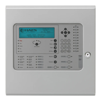
Use button 1 to move the fi re LED to zone 3.
Use button 1 to move the fi re LED to zone 3.
to enter ‘edit mode’ and zone 3 fi re LED will pulse.
to enter ‘edit mode’ and zone 3 fi re LED will pulse.
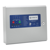
Now use button 2 to switch on
Now use button 2 to switch on
compatibility mode. The zone 1
compatibility mode. The zone 1 Fault LED will illuminate indicating
that the compatibility mode is set to on,
Pressing button 2 again will toggle the compatibility mode on & off,
Pressing button 2 again will toggle the compatibility mode on & off,
indicated by the zone 1 Fault LED.
Press and hold button 1 for 3 seconds to save the settings and exit the programming mode.
Enter the next programming code or disable the controls and return DIL switch 3 to ‘OFF’.
The above setting is only relevant if you are using
The above setting is only relevant if you are using
using Apollo Series 65 detectors.
using Apollo Series 65 detectors.
RESOUND SILENCE RESET
ENTER
1234
Disable
Mode
Test
Mode
Mute
Buzzer
Test
Lamps
RESOUND SILENCE RESET
ENTER
1234
Disable
Mode
Test
Mode
Mute
Buzzer
Test
Lamps
RESOUND SILENCE RESET
ENTER
1234
Disable
Mode
Test
Mode
Mute
Buzzer
Test
Lamps