Excel-EN Installation, Commissioning & Operating Manual Approved Document Ref: UI-XLEN-01 Issue 7.0
46
SETUP & PROGRAMMING
4 2 4 4
Relay & Output Functional Options
Each of the relays and switched -ve outputs on the main circuit board and high spec zone extension cards
can be independently programmed with a custom response to; Silence Alarms (including, Silence button
or input programmed for remote Silence Alarms), Evacuate (including, Resound button, input programmed
for Evacuate or 220Ω ‘Evacuate’ call point), Class Change Input, Alert Input or during Zone Delays.
Note:- (Before any programming can be applied to the outputs on the main circuit board, they must
fi rst be made programmable. See programming option 4-1-4-2).
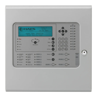
Enter the code, 4-2-4-4 and press the ENTER button.
The zone 1 fi re LED will light. This indicates the output to be programmed
as per the table below.
RESOUND SILENCE RESET
ENTER
1234
Disable
Mode
Test
Mode
Mute
Buzzer
Test
Lamps
RESOUND SILENCE RESET
ENTER
1234
Disable
Mode
Test
Mode
Mute
Buzzer
Test
Lamps
LED 1 LED 2 LED 3 LED 4 LED 5 LED 6 LED 7 LED 8 LED 9 LED 10
Fire
Relay
(Main
PCB)
Fault
Relay
(Main
PCB)
Fire O/P
(Main
PCB)
Fault
O/P
(Main
PCB)
OPA
Zone
ext card
1 (Zones
5 - 8)
OPB
Zone
ext card
1 (Zones
5 - 8)
Aux
Relay
Zone
ext card
1 (Zones
5 - 8)
OPA
Zone
ext card
2 (Zones
9 - 12)
OPB
Zone
ext card
2 (Zones
9 - 12)
Aux
Relay
Zone
ext card
2 (Zones
9 - 12)
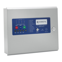
Use button 2 to change the response for the output as per table above,
indicated by the amber, fault LED, ON or OFF. Then use button 1 to move to
the next function if required.
* Fault relay & output default to ‘OFF’
Press the ENTER button to return back to the output selection, indicated by a steady zone fi re LED
When fi nished, press and hold Button 1 for 3 seconds to save setting and exit programming mode.
RESOUND SILENCE RESET
ENTER
1234
Disable
Mode
Test
Mode
Mute
Buzzer
Test
Lamps
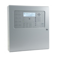
Use button 1 to move the fi re LED to the output that requires editing.
With the required output for editing LED lit, press the ENTER button to
enter ‘editing mode’.
The fi re zone 1 LED will now pulse to indicate setting the selected
output’s response to the fi rst function (Resets on Silence Alarms).
Use button 1 to scroll to the function that requires editing for that output, inidicated by a pulsing fi re LED
1 - 5 as per table below.
Fire LED
(pulsing)
LED 1 LED 2 LED 3 LED 4 LED 5
Function
Resets on
Silence
Alarms
Activates
on
Evacuate
Activates
on Class
Change
Activates
on Alert
Activates
During
Delay
Amber
fault LED
(default
setting)
OFF ON * OFF OFF OFF