Excel-EN Installation, Commissioning & Operating Manual Approved Document Ref: UI-XLEN-01 Issue 7.0
47
SETUP & PROGRAMMING
Press the ENTER button to return back to the Twin Wire sounder circuit selection, indicated by a steady
zone fi re LED.
When fi nished, press and hold Button 1 for 3 seconds to save setting and exit programming mode.
Press the ENTER button to return back to the sounder circuit selection, indicated by a steady zone fi re
LED.
When fi nished, press and hold Button 1 for 3 seconds to save setting and exit programming mode.
Fire LED
(pulsing)
LED 1 LED 2 LED 3 LED 4 LED 5
Function
Silences
on Silence
Alarms
Sounds on
Evacuate
Sounds
on Class
Change
Sounds on
Alert
Sounds
During
Delay
Amber
fault LED
(default
setting)
ON ON ON ON OFF
3
4
1
3
2
4
3
4
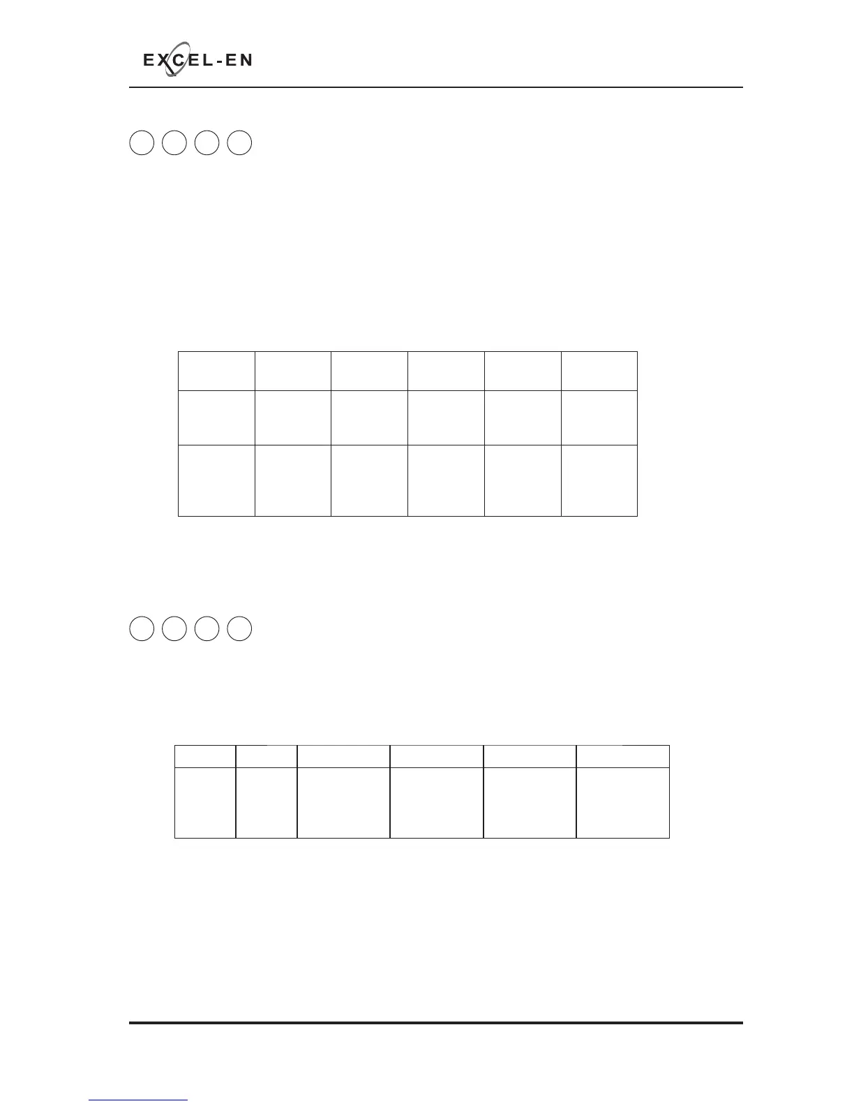
Twin Wire Sounder Circuit Functional Options
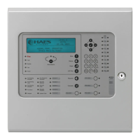
Conventional Sounder Circuit Functional Options
If using Twin Wire zones, the sounders on each of the Twin Wire circuits can be programmed with a custom
response to various panel functions in the same way as the relays and switched -ve outputs.
The process is exactly the same as with the relays & switched -ve outputs, but using the above code.
I.e. Use button 1 to select the Twin Wire sounder circuit fi rst (indicated by a steady fi re zone LED), press
ENTER and then use button 1 to select the function that requires editing for that sounder circuit (indicated
by a pulsing fi re zone LED) as per table below.
Use button 2 to edit the response indicated by the amber, fault LED, ON or OFF.
To programme each of the conventional sounder circuits on the main circuit board and high spec zone
extension cards with same custom reponses as above, the process is exactly the same but using the code
4-3-4-4.
I.e. Use button 1 to select the sounder circuit fi rst (indicated by a steady fi re zone LED) as per table below.
Press ENTER and then use button 1 to select the function that requires editing for that sounder circuit
(indicated by a pulsing fi re zone LED) as per the sounder CCT function table in the Twin Wire settings
above.
Use button 2 to edit the response indicated by the amber, fault LED, ON or OFF.
LED 1 LED 2 LED 3 LED 4 LED 5 LED 6
SNDR1
(Main
PCB)
SNDR2
(Main
PCB)
SNDR A.
Zone ext card
1 (Zones 5
- 8)
SNDR B.
Zone ext card
1 (Zones 5
- 8)
SNDR A.
Zone ext card
2 (Zones 9 -
12)
SNDR B.
Zone ext card
2 (Zones 9 -
12)
Sounder CCT
function table