Excel-EN Installation, Commissioning & Operating Manual Approved Document Ref: UI-XLEN-01 Issue 7.0
52
SETUP & PROGRAMMING
REPEATER PANEL SETUP & PROGRAMMING
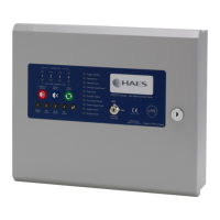
The panel can support up to 8, fully functional repeater panels on the network which can be either the 12
way repeater panels or Remote Display Units or a combination of both. N.B. The 12 way repeater panel
will only display the fi rst 12 zones of any network system.
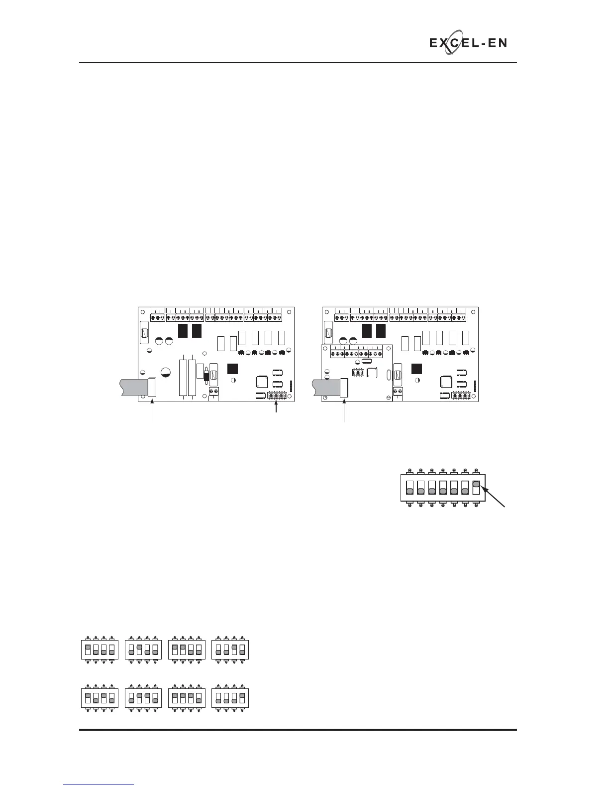
Repeater Comms PCB
To run repeaters, a Comms PCB (TPCA05) must be fi tted to the control panel. The repeater panels are
supplied with the comms board fi tted.
The Comms PCB fi ts into the control panel on top of the main circuit board where the ribbon cable from
the display board is normally plugged.
To fi t the Comms PCB, power down the panel, un-plug the display board ribbon cable from the main circuit
board and plug the Comms PCB into the socket instead.
A socket is provided on the top of the Comms PCB to re-connect the display board ribbon cable.
Once the Comms PCB has been fi tted, switch 7 on the 7 way DIL switch located on the main circuit board
should be switched to the ON position.
With this switch in the ON position the panel will automatically recognise &
operate the Comms PCB (TPCA05).
Next, the panel will need to be programmed for the number of repeater panels on the system. See panel
wide settings 2-1-2-3 option 2 (Set Number of Repeater Panels on System).
Addressing
Each repeater panel needs to have a seperate address. The addressing is done using the 4 DIL switches
on each of the Comms PCBs using binary code values, see diagram below.
The address should be set in sequence from 1 - 8, fi rst repeater address 01, next repeater address 02 etc.
The control panel should always be address 00 (all switches off).
PSU
@+
+
-- +-
+-
+- +- +-+- +-
28V 0V
C NC NO C NC NO
FIRE FAULT
FR
FLT
CC
PUL
-OP -OP -IP -IP
SNDR1 SNDR2 ZONE1 ZONE2 ZONE3 ZONE4
BATTERY
PSU
@+
+
-- +-
+-
+- +- +-+- +-
28V 0V
C NC NO C NC NO
FIRE FAULT
FR
FLT
CC
PUL
-OP -OP -IP -IP
SNDR1 SNDR2 ZONE1 ZONE2 ZONE3 ZONE4
BATTERY
COMS A COMS B 28
V+
SW -ve OUTPUTS
+-
+-
12345 6
1 2 34
ON
ADDRESS
Disconnect display board ribbon cable
7 way DIL switch
Plug Comms PCB into the socket and
re-connect dispay board ribbon cable to
socket on top of Comms PCB
1 2 345
67
ON
1 2 345
67
ON
1 2 34
ON
ADD 01
1 2 34
ON
ADD 02
1 2 34
ON
ADD 03
1 2 34
ON
ADD 04
1 2 34
ON
ADD 05
1 2 34
ON
ADD 06
1 2 34
ON
ADD 07
1 2 34
ON
ADD 08
ON = Network/
Repeater mode
1 2 345
67
ON
Network System Note:
Repeater panel addresses are parallel to network slave
panel addresses on a network system.
I.e. a repeater and a network slave panel can both have
address 01 on the network.