Excel-EN Installation, Commissioning & Operating Manual Approved Document Ref: UI-XLEN-01 Issue 7.0
53
SETUP & PROGRAMMING
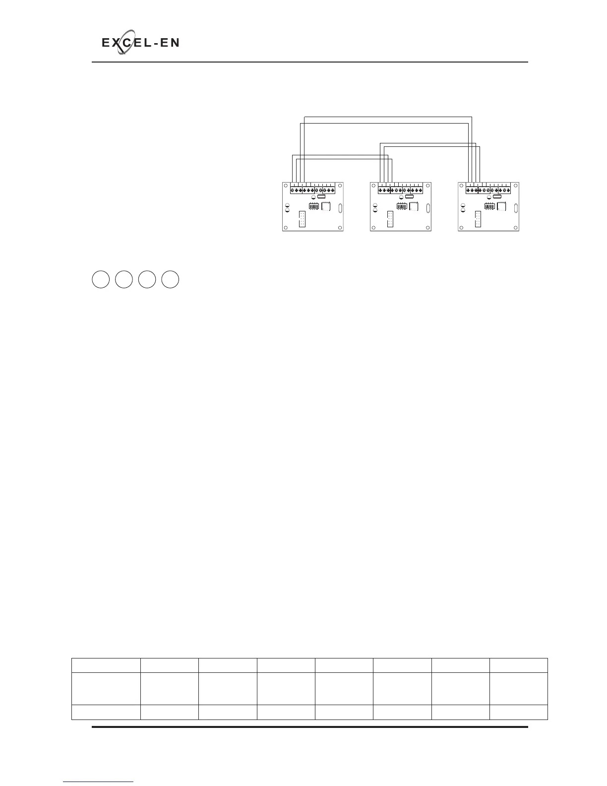
Wiring
The repeater panels are designed to be
wired in a fault tolerant (fail safe) loop
confi guration, from comms A to B and
back to the main panel again (see diagram).
This enables repeater panels to still work if
there is a break in the cables.
If replacing an older system where the
existing cabling cannot be confi gured in
a loop as shown, it is possible to change
the panel back to radial circuit comms
monitoring. See panel wide settings 2-1-
2-3 option 6 (Repeater Comms Monitoring Type).
COMS A COMS B 28
V+
SW -ve OUTPUTS
+-
+-
12345 6
1 2 34
ON
ADDRESS
COMS A COMS B 28
V+
SW -ve OUTPUTS
+-
+-
12345 6
1 2 34
ON
ADDRESS
COMS A COMS B 28
V+
SW -ve OUTPUTS
+-
+-
12345 6
1 2 34
ON
ADDRESS
Fault Tolerant Loop Wiring
Main Panel Repeater/Network Panel 1 Repeater/Network Panel 2
4 4 4 3
Programming Repeater Panels
Programming of all the repeater panels is done from the main control panel.
The repeater panels have 2 inputs located on the main circuit board, Class Change (CC) and Alert (PUL).
Switching a negative voltage into these inputs will cause the alarm sounders to operate. The Class Change
input (CC) will cause the alarms to sound continously and the Alert input (PUL) will cause the alarms to
pulse.
There are also 6 switch -ve outputs located on the Comms PCB. By default o/p 1 is set to activate on
common fi re and o/p 2 is set to activate for common fault.
There are 4 programming options available for the inputs and outputs in the repeater panels.
• Outputs 1 - 6 activate on common fi re
• Outputs 1 - 6 activate zonally for zones 1 - 6
• Outputs 1 - 6 activate zonally for zones 7 - 12
• Change inputs CC & PUL to power supply fault inputs.
It is also possible in this programming mode to disable the controls on repeater panels, making them
passive instead of active and to disable the battery monitoring on the repeater panel if no battery backup
is required.
Enter the above code and press ENTER. The zone 1 fi re LED will light. This indicates which repeater panel
is to be programmed 1 - 8. Use button 1 to move the fi re zone LED to the required repeater.
With the required repeater for editing LED lit, press the ENTER button to enter ‘editing mode’. The fi re zone
1 LED will now pulse to indicate setting of attribute 1 (outputs 1 - 6 common fi re) for that repeater.
Use button 1 to scroll to the attribute that requires editing, inidicated by a pulsing fi re LED 1 - 7 as per
table below. Now use button 2 to change the setting indicated by the amber, fault LEDs, ON or OFF. Then
use button 1 again to move to the next attribute if required. See repeater instruction manual for further
details of option 7
Fire LED (pulsing) LED 1 LED 2 LED 3 LED 4 LED 5 LED 6 LED 7
Attribute
O/P 1 - 6
Common Fire
O/P 1 - 6
Zonal (Zones
1 - 6)
O/P 1 - 6
Zonal (Zones
7 - 12)
Inputs For
PSU Fault
Controls
Passive
Disable Battery
Monitoring
Repeater
Mimic Display
Mode
Default Setting OFF OFF OFF OFF OFF OFF OFF