02
T +33 (0) 3 88 02 87 00 info@hager.com hager.com | 2023-11
Warning
Electric shock if live parts are
touched!
An electric shock can lead to
death!
•
Isolate all connection cables
before working on the device
and cover any live parts in the
area!
•
Break out one of the pre-punched
cable entries
7
on the bottom/rear side
of the housing base
10
.
•
Push the connection cables through
the supplied rubber seal
11
and plug
the seal into the broken out cable entry
7
.
•
Fasten the housing base
10
to the in-
stallation surface with two screws (not
in scope of delivery).
•
Connect according to the wiring dia-
gram.
•
Screw the module
9
to the base
10
and attach the cover
8
.
•
Switch on circuit breaker.
Information
When the voltage is applied, the
quartz workings only start after a
few minutes.
The full battery power reserve is
only achieved after 2 days.
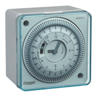
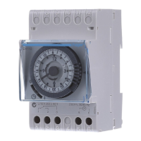
Settings
•
Current time: Turn the switching disk
4
in a clockwise direction until the
marking
1
(arrow) and the printed hour
hand
3
display the current hour.
•
Then, turn the minute hand
3
in a
clockwise direction with your finger
until the current time
2
has been set
(Figure 01).
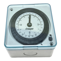
•
Define the switching times by radially
pulling out (ON) or pushing in (OFF) the
switching segments
5
(Figure02).
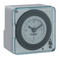
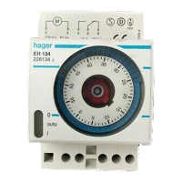
•
Selecting the operating mode
6
(Fig-
ure03):
= Auto, 1 = Continuous ON,
0 = Continuous OFF
Technical data
Operating voltage .............. 230 V~, +10 %/-15 %
240 V~, +/- 6%
Frequency ............................................. 50 - 60 Hz
Cycle .......................................................24 hours
Shortest switching time ....................... 15 minutes
Power consumption ........................... max. 0.7 W
Switching capacity ..................13 A, 250 V~, AC1
Inductive load ................. 8 A, 250 V~, cos ϕ = 0.6
Switching capacity min. ................24 V~, 100 mA
zSafety instructions
Electrical equipment may only be installed
and assembled by a qualified electrician in
accordance with the relevant installation
standards, regulations, directives and
safety and accident prevention regulation
of the country.
Failure to comply with these installation
instructions may result in damage to the
device, fire or other hazards.
These instructions are an integral compo-
nent of the product and must be retained
for the end user.
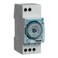
Function
− Analogue day timer
− 1 channel
Correct use
− For lighting, ventilators, fountains, adver-
tising or similar applications
− For use in closed, dry interior areas
or weather-proof condition and mois-
ture-protected exterior areas
− Installation on a flat substrate (wall)
− Switching of any phase conductor is
permitted, switching of SELV is not
permitted
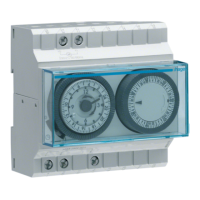
Design and layout of the
device (Figure 01)
1
Marking for setting the current hour (oppo-
site)
2
Clock face for the current time
3
Hands for minutes and hours (printed)
4
Switching disk to display the switching
times
5
Switching segments, each 15’
6
Switch for operating mode:
= Auto/ 1 = Continuous ON/ 0 = Conti-
nuous OFF
7
Cable entries
8
Transparent cover
9
Time switch module
10
Housing base
11
Sealing
Installation and electrical
connection
•
Remove the transparent cover
8
.
•
Remove the time switch module
9
from housing base
10
.
LED lamps
− ≤ 2 W ........................................................ 25 W
− > 2 W ........................................................ 70 W
Incandescent/halogen lamps ................... 1600 W
Fluorescent lamps:
− Uncompensated .................................... 460 VA
Power reserve ................. 72 h, after 48 h at 20 °C
Accuracy .............................. ±1.5 s/day at +20 °C
Cable cross-section:
− At 10 A .................................. max. 2 x 1.5 mm²
− At 13 A .................................. max. 2 x 2.5 mm²
Miniature circuit breaker ........................10 A/13 A
Contact ................................Change-over contact
Opening width ..................................... < 3 mm (μ)
Protection class ...................................................II
Degree of protection: .................................... IP20
Additional protection
With seal and cover assembled
product provides protection
against small objects and drip-
ping water.
Operating temperature (at 13 A) .. –10 °C - +45 °C
Storage temperature .................... –25 °C - +60 °C
Rated surge voltage .......................................4 kV
Operating altitude .................................. < 2000 m
Contamination level .............................................2
Mode of action ......................................... 1 BSTU
Correct disposal of this product
(Waste Electrical & Electronic
Equipment)
(Applicable in the European Union and other
European countries with separate collection
systems).
The identification shown on the product or its doc-
umentation indicates that it should not be disposed
of with other household waste at the end of its
working life. To prevent possible harm to the envi-
ronment or human health, please dispose of this
device separately from other types of waste. This
helps you to promote sustainable reuse of material
resources.
Private consumers are asked to contact the dealer
from whom they purchased the product, or their
local administration, to obtain information on
how to dispose the product in an environmental-
ly-friendly manner. Commercial consumers are
asked to contact their suppliers and to check the
general terms and conditions of business of the
purchasing agreement. This product should not be
mixed with other commercial waste for disposal.
 Loading...