20
0
50
100
150
200
250
300
350
400
450
-300 -250 -200 -150 -100 -50 0 50 100 150 200
a (mm)
Fr (kN)
0
5000
10000
15000
20000
25000
30000
35000
40000
45000
50000
55000
60000
65000
70000
75000
80000
85000
90000
95000
100000
Fr (lbf)
10 rpm
40 rpm
0
50
100
150
200
250
-300 -250 -200 -150 -100 -50 0 50 100 150 200
a (mm)
Fr (kN)
0
5000
10000
15000
20000
25000
30000
35000
40000
45000
50000
55000
Fr (lbf)
20 rpm
90 rpm
0
50
100
150
200
250
-100 -50 0 50 100 150 200
a (mm)
Fr (kN)
0
5000
10000
15000
20000
25000
30000
35000
40000
45000
50000
55000
Fr (lbf)
20 rpm
90 rpm
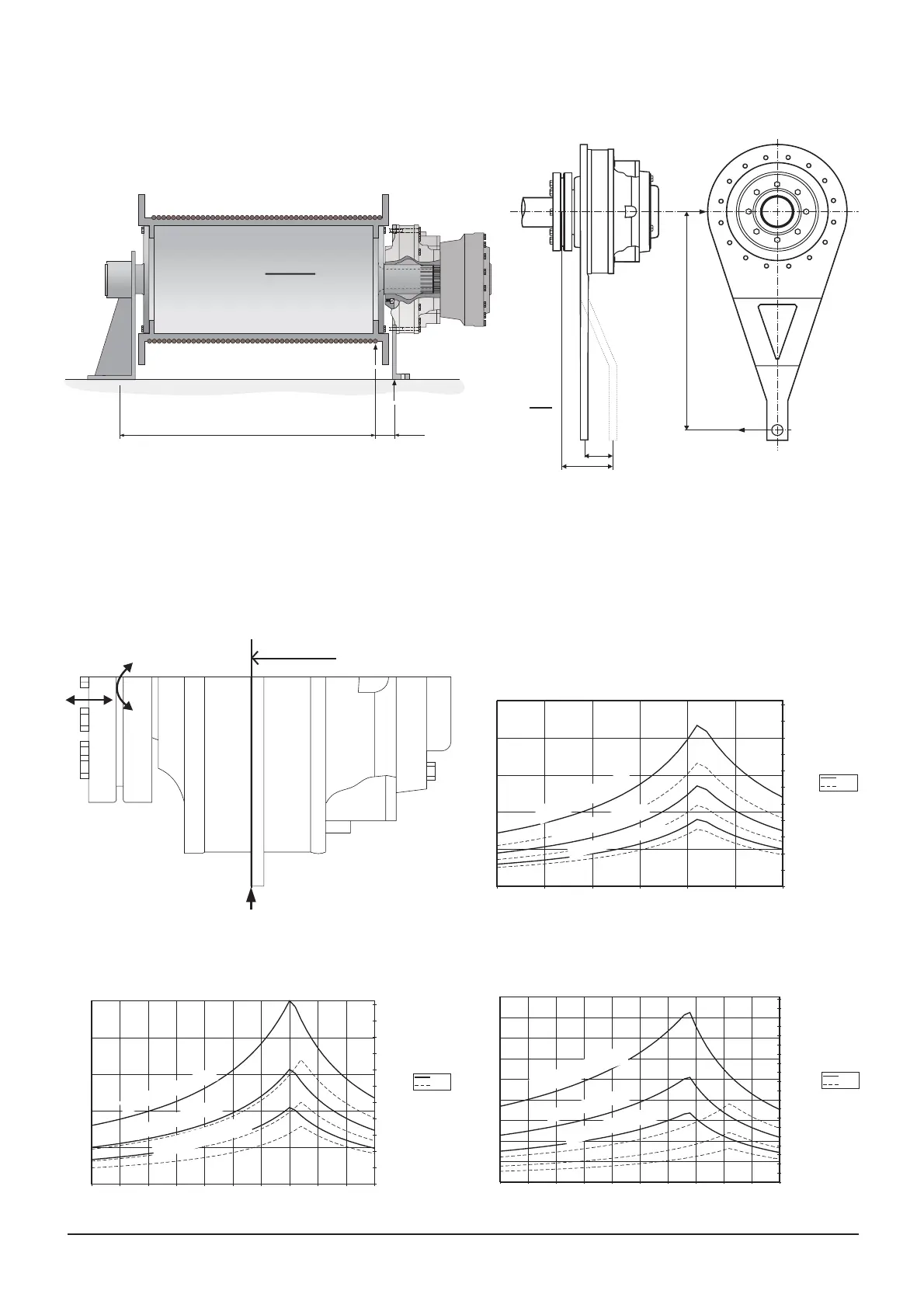
Recommended external loads for Compact
If not standard torque arms TCA are used, forces
must be checked for main bearings and coupling.
a = 0 mm
F
r
(kN)
F
r
(lbf)
Diagram 33 Motor type CA 100 and CA 140
F
r
(kN)
F
r
(lbf)
Diagram 34 Motor type CA 210
L
10h
= 1000 hrs.
L
10h
= 5000 hrs.
L
10h
= 20000 hrs.
L
1
0h
= 1000 hrs.
F
r
(kN)
F
r
(lbf)
Diagram 32 Motor type CA 50 and CA 70
Fixed shaft - torque arm mounted motor, viscosity 40/250 cSt, speed 100 rpm.
Torque arm is mounted at a = 0 mm on the motor.
Note: When Bracket mounted motor or higher external load, please contact Hägg lunds representative.
Permissible external loads
- The bracket must be designed so it does not give
extra external forces to the motor.
Motor mounted in winch - reaction forces.
F
r
= Total radial force on fi xed motor mounting
F
a
= Axial force acting on motor centerline
T = Output torque for motor
M
b
= Bending mo ment acting on hollow shaft
F
r
=
T
l
M
b
= F
r
· a
L
2
L
1
F
r
F
F
r
= F ·
L
1
+ L
2
L
2
F
r
F
r
a
l
F
a
M
b
F
r
L
1
0h
= 5000 hrs.
L
10h
= 20000 hrs.
L
1
0h
= 1000 hrs.
L
10h
= 5000 hrs.
L
10h
= 20000 hrs.
 Loading...