INSTALLATION
PAGE
ENGLISH
Step 4.2Step 4.1
Step 4.3
Table 1
Step 3.3
Step 3.4
Half union
Flare nut
Torque wrench
Spanner
Forced fastening without careful centering may
damage the threads and cause a leakage of gas.
Liquid side6.35mm(1/4") 18N.m/13.3Ft.lbs
Liquid/Gas side9.52mm(3/8") 42 N.m/30.1Ft.lbs
Gas side 12.7mm(1/2") 55N.m/40.6Ft.lbs
Gas side 15.88mm(5/8") 60 N.m/44.3Ft.lbs
Outdoor unit
Indoor unit
A
B
Outdoor unit
Indoor unit
A
B
A
B
Outdoor unit
Indoor unit
Oil trap
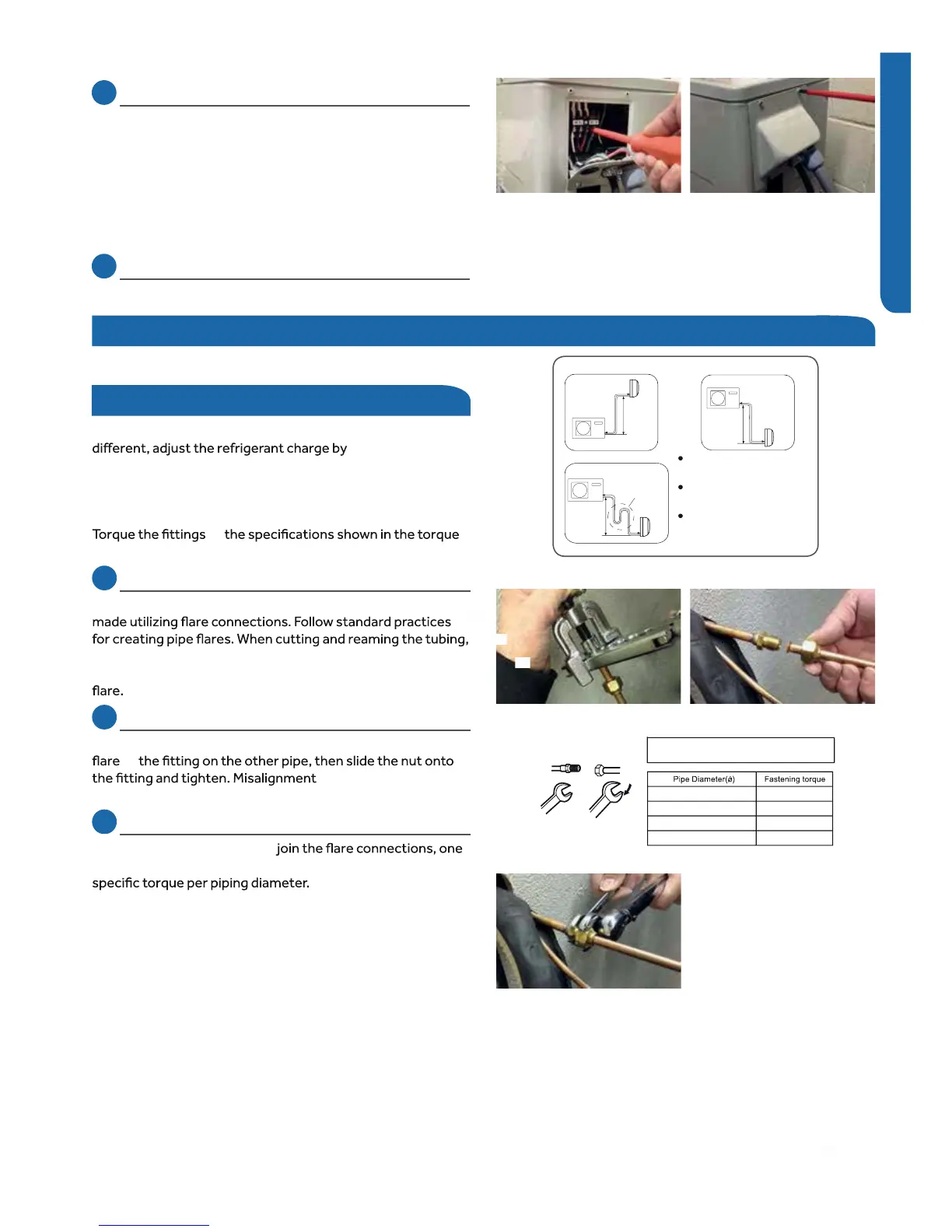
CAUTION
Max. Elevation: A Max
= 33ft / 10m (09k / 12k)
= 50ft / 15m (18k / 24k)
In case the height of A is more than
15ft / 5m, an oil trap should be
installed every 16-23ft /5-7m
Max. Length: B Max
=50ft/15m(Advanced 9k/12k)
=66ft/20m(Tempo 9k/12k)
=83ft/25m(18k/24k)
Illustration 4
Step 4 - Interconnecting the Indoor and Outdoor Units
Piping
The standard lineset length is 25ft. If the installation length is
oz /ft. for the 9K,
12K, 18K, and 24K model. (Illustr ation 4)
to
chart.
4.1
Step - 4.1
Refrigerant piping connections for the mini-split system are
use caution to prevent dirt or debris from entering the tubing.
Remember to place the nut on the pipe before creating the
4.2
Step - 4.2
To join the line set to the service valve, directly align the piping
to
may result in a leaking
connection.
2.17
Step - 4.3
Two wrenches are required to
standard wrench, and one torque wrench. See Table 1 for the
*See Steps 2.11 - 2.13 & 3.2 - 3.4 for connecting the
electrical.
3.3
Step - 3.3
Connect the wiring for both the power source and indoor
wiring.
Wire the system according to applicable national / local
codes.
Verify that the wiring connections for the indoor unit match
wire for wire.
(1-1, 2-2, 3-3, Gnd-Gnd). Failure to wire the system correctly
may lead to improper operation or component damage.
3.4
Step - 3.4
Replace the cover plate.
37
0.2
service valves.
 Loading...