49-7835 Rev. 8 13
ENGLISH
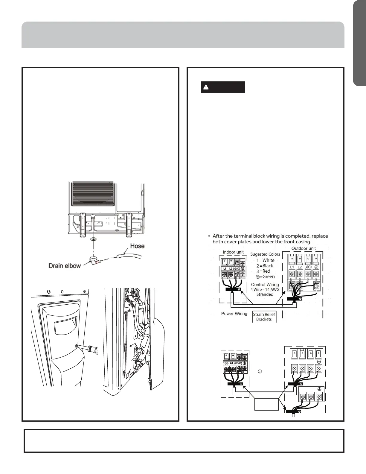
A. Prepare the Outdoor Unit for Installation
• Remove all packaging.
• Place supplied vibration pads onto outdoor unit’s
feet.
• Attach the supplied drain elbow to the outdoor
unit if required. Connect extension piping as
needed (not supplied). (see illustration)
NOTE: The drain elbow is designed with an
air gap and will not sit flush to bottom of the
outdoor unit.
NOTE: 1U09AP*, 1U12AP*, 1U15AP*, 1U18AP*
and 1U24AP* models will not use a drain
elbow. A 3rd party pan is needed if condensate
management is required by code.
• Remove the cover plate of the outdoor unit to
expose the terminal block connections.
B. Electrical Connections for the Outdoor Unit
WARNING
RISK OF ELECTRIC SHOCK.
Could cause injury or death.
Make sure power is off before touching wires.
NOTE: Be certain all wiring complies with local
building codes and NEC and that the supply
voltage for this system is correct.
• Connect the wiring for both the power source
and the indoor wiring using a conduit cable
bracket on the side of the outdoor unit.
• Using a wire stripper, remove the insulation and
separate the wires.
• Verify that the wiring connections match the
indoor connections wire for wire.
• Ensure each wire is under the screw terminal
plate and the plate is tightened.
• Ensure the 14/4 control cable is secured under
the strain relief bracket.
• Verify that all connections are secured
1. Remove Screw 2. Slide the panel down to
release the clips and pull
away.
Step 3 - Installation of the Outdoor Unit
NOTE: Failure to follow the wiring guidelines can result in control board damage and communication issues (E7 error
code). This includes improper wire size, use of solid core wire, midline splicing and poor terminal connections.
INSTALLATION INSTRUCTIONS
3
2
1
)
(
C
L2
L1
Indoor unit
Control Wiring
4 Wire - 14 AWG
Stranded
1
2
3
=White
=Black
=Red
=Green
Sugested Colors
Strain Relief
Brackets
*Tempo 230V series
*NextGen Arctic Series
 Loading...