TECHNICAL OVERVIEW
PAGE 35
ENGLISH
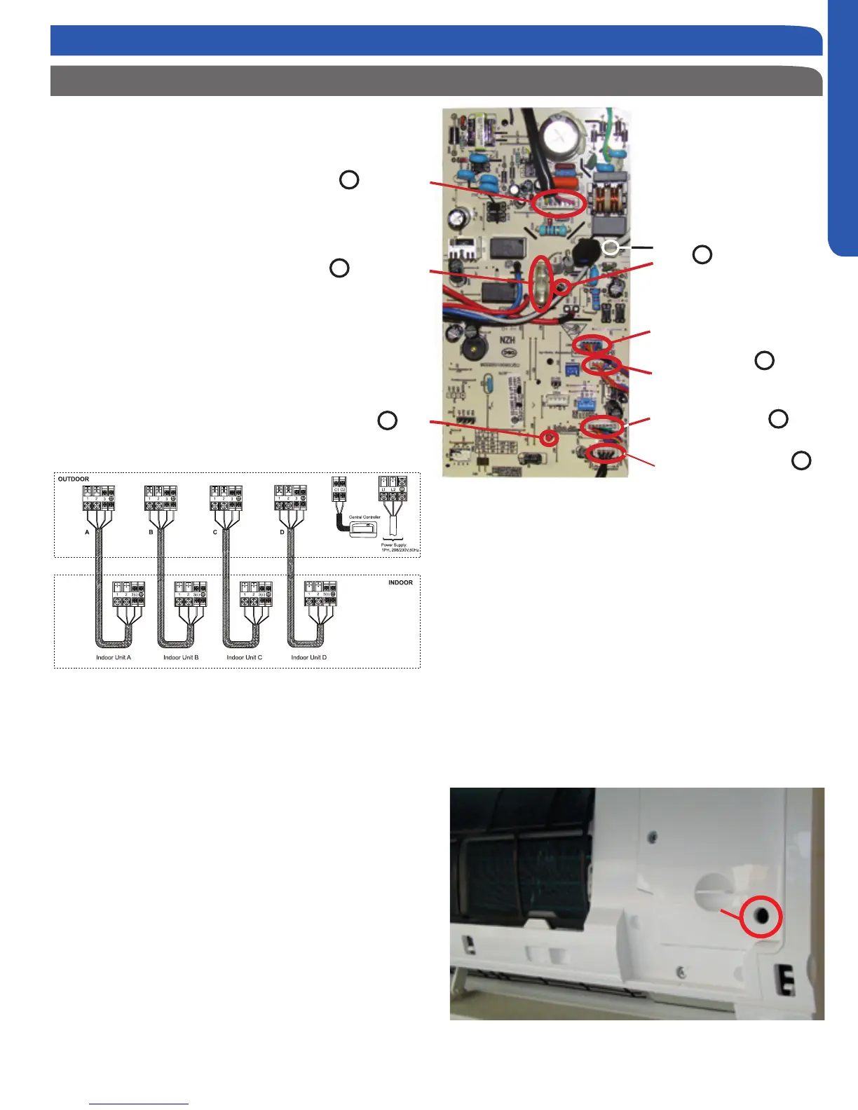
INDOOR UNIT TECHNICAL OVERVIEW
The Indoor Unit Circuit Board communicates
with the outdoor unit ECU via a connection at
Terminal Block screw 3.
The data pulse that sends the communi-
cation information can be measured with a
voltmeter placed to DCV range. From the
ground connection at the Terminal Block to
the Number 3 screw connection, the voltage
should pulse up and down when data is being
transmitted.
This control board has control over the fan
louver movement, manual fan blower control,
indoor coil temperature and indoor air tem-
perature sensing functions. All operational
decisions are controlled by the OUTDOOR
UNIT ECU. The connections on the indoor
indoor board are shown here in the schematic
drawing.
Line voltage to power the indoor unit comes in on Terminal
Block connections 1 and 2. Power connects from these termi-
nal connections to CN- 52 and CN-21 on the circuit board. If
the board does not respond to commands and has no display,
check for line voltage at these connections. When power is
present at the indoor board, the RED LED on the circuit board
will blink a 2 ash code.
The control board has a replaceable 3.15A 250V fuse that
protects against excessive current. If power is present at
the board but the board does not work, check for continuity
through the fuse. Replace if the fuse is open.
The indoor unit temperature sensors are connected at Plug
CN6. When testing the calibration of these sensors, the wires
can be released from the plug by pressing on the tension tab
on the side of the plug.
The receiver/display unit that is mounted to the front cover of
the indoor unit plugs into the circuit board via a connection at
Plug CN-7.
Indoor Wall Mount Unit Circuit Board
There are two to three motors that control the movement of
the louvers right, left and up/down. These motors connect at
CN5, CN11 and CN10. Some units will use one motor to oper-
ate the right and left movement function.
The blower motor is connected to the circuit board at plug
CN-9.
There is an Emergency Run switch on the edge of the indoor
board that will put the system into Auto Mode should the re-
mote control break or be lost. When this switch is pressed and
held for 5 seconds, the indoor unit display will beep twice and
the system will enter TEST MODE.
Receiver / Display
Horizontal Louver
Stepper Motorr
LED
Temperature Sensors
Fan Motor
3.15A 250V
Fuse
Vertical Louvers
Stepper Motor
7
2
3
4
5
6
CN52
CN21
1
Emergency Run
Switch
 Loading...
