Service diagnosis
11.4.1 Thermistor or Related Abnormality
Indoor Display E1: Room temperature sensor failure
E2: Heat-exchange sensor failure
Outdoor display LED1 flash 10 times
Defrost temperature sensor failure
LED1 flash 11 times
Suction temperature sensor failure
LED1 flash 12 times
Ambient temperature sensor failure
LED1 flash 13 times
Discharge temperature sensor failure
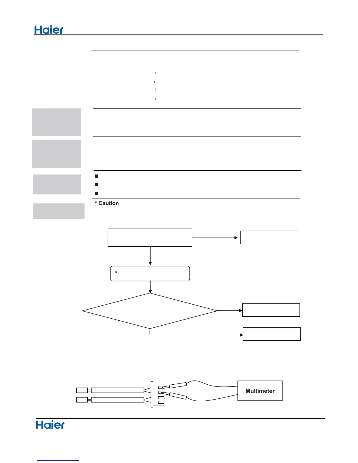
*Thermistor resistance check method:
Remo
ve the connector of the thermistor on the PCB, and measure the resistance of thermistor using
tester.The relationship between normal temperature and resistance is shown in the value of indoor
thermistor.
Domestic air conditioner
Thermistor resistance check
YES
NO
YES
Check the connector connection,
whether if it loose or misplug
Re-connect
NO
Replace the thermistor
Replace the indoor PCB
Is the resistance is conformity
with normal temperature
Method of
malfunction
detection
Malfunction
detection
conditions
Supposed
causes
Troubleshooting
The temperatures are detected by the thermistror which are used to
determine the errors
When the thermistor input voltage is more than 4.92V or less than 0.08V
during compressor operation
Ɣ1RWH The values vary slightly in some models
Faulty connector connection
Faulty thermistor
Faulty PCB
Be sure to turn off power switch before connect or disconnect connector, or
else
parts damage may be caused
36
 Loading...