User Manual
4. Installation
20
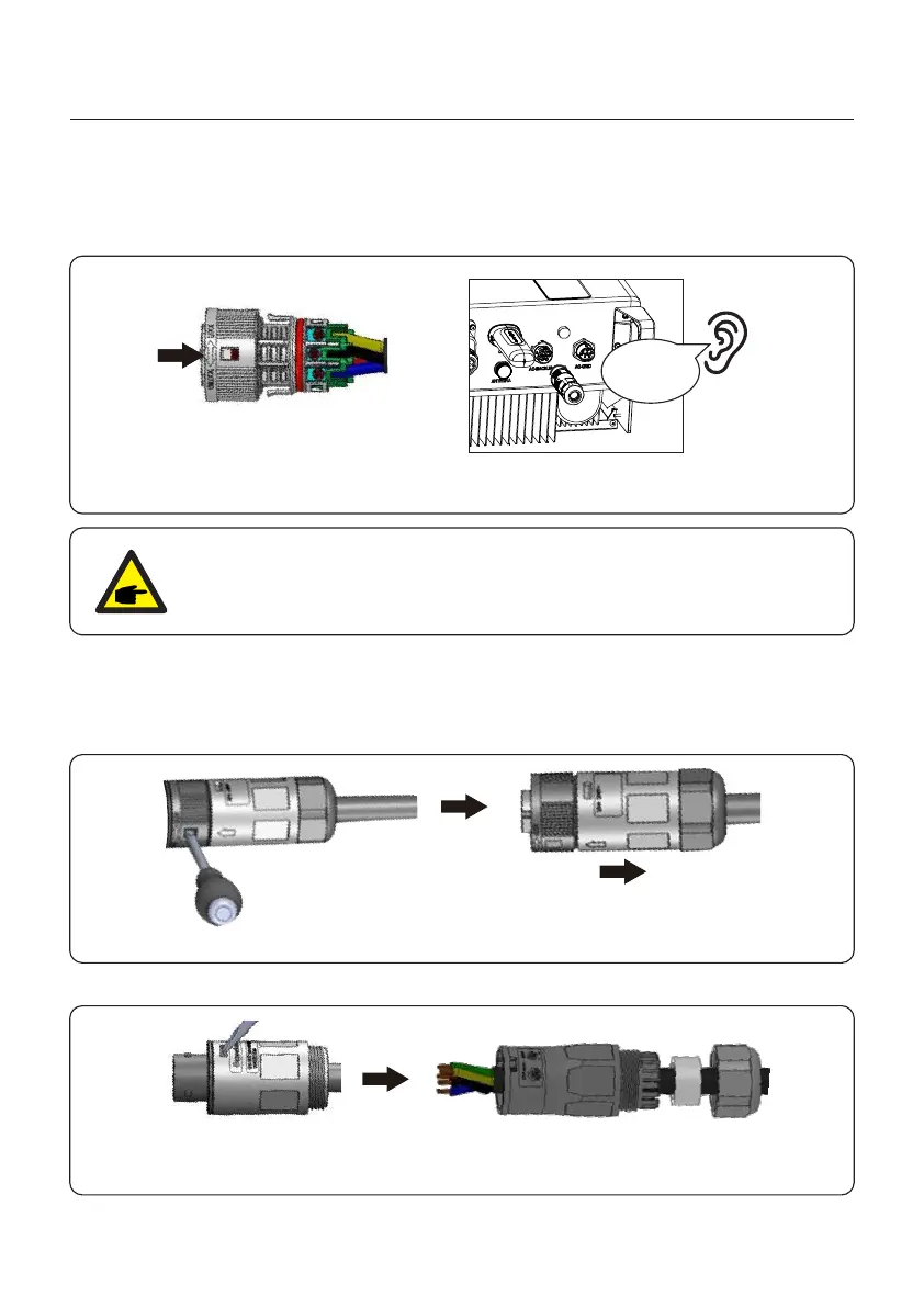
Figure 4.28
NOTE:
A continuity test shall be made to ensure that the correct terminations have
been made after field wiring.
6. Push the AC Backup Connector into the AC Backup Port on the inverter and rotate the
rotatory ring on the AC Backup connector to the direction as marked “LOCK” on the
connector. (Hold the Body while rotating the ring).
Click
4.6.3 Disassembly Connector
1. Separate the male and female connector, rotate the locker according to the direction
instructed by the marks on the locker.
2. Disassembling body and housing for rewire.
Figure 4.29
Figure 4.30
 Loading...