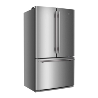
SERVICE MANUAL
Model: HB21FC45N*
3
Issue 2010-07-05
Rev. Ref1007S019V0
4-9.Celsius/Fahrenheit conversion function ······························································· 21
4-10.The water filter indicator setting ········································································· 22
4-11.Energy saver ····································································································· 22
4-12.Demo mode ······································································································· 22
5.
Control principle ······································································································ 23
5-1. Air Damper ········································································································ 23
5-2. Control principle of fan motor ············································································ 23
5-3. Defrost control ·································································································· 23
5-4. Control principle of Ice-maker ··········································································· 24
5-5.Ice- making process ··························································································· 25
5-6.TEST mode functions ························································································· 26
6. System flow principle ······························································································· 27
6-1. System flow scenograph ··················································································· 27
7. Circuit diagram·········································································································· 28
7-1. Main control PCB diagram ················································································ 28
7-2. Brief principle diagram ······················································································ 31
7-3.Sensor and error code ······················································································· 32
8. Water line map ··········································································································· 34
8-1.The water line sketch map ················································································· 34
8-2.Water line scenograph ······················································································· 35
9. Trouble shooting ······································································································· 36
9-1.Trouble shooting and repair ··············································································· 36
9-2.No making ice ···································································································· 38
9-3.Ice glomeration ··································································································· 38
9-4.The error code ···································································································· 39
9-5.Instruction of check variable speed compressor ················································ 43
9-6.Poor cooling, big noise ······················································································· 44

 Loading...