INSTALLATION
PAGE 4
ENGLISH
Illustration 2
Illustration 3
2.9
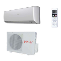
Step 2.9
With the top of the indoor unit closer to the wall, hang the
indoor unit on the upper hooks of the mounting plate. Slide
the unit slightly side to side to verify proper placement of the
of the indoor unit to the mounting plate, and lower the unit
onto the lower hooks of the mounting plate. (Illustration 2)
Verify the unit is secure.
2.10
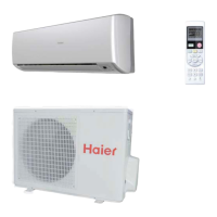
Step - 2.10
Slightly raise the entire unit vertically, pull the lower portion
the upper hooks of the wall plate.
Step 2.9
Step 2.10
Step 2.11A
Step 2.12
Step 2.13B
Step 2.11B
Step 2.13A
mounting plate
3
2
Power
Wiring
1
)
(
N
)
(L
)
(
C
3
2
1
)
(
N
)
(
L
)
(
C
Indoor unit
3wire 14AWG
Control Wiring
Outdoor unit
3
2
Power
Wiring
1
)
(
N
)
(L
)
(
C
2
1
)
(
N
)
(
L
Indoor uni
t
3wire 14AWG
Control Wiring
(Heat Pump models only)
3.1
Step - 3.1
do so prior to attaching the refrigerant lines and wiring.
Step 3.2
Step 3.1
Mounting the Indoor Unit Onto the Wall Plate
Electrical Connections for the Indoor Unit
2.11
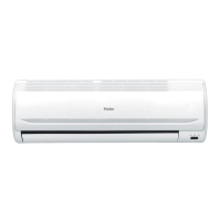
Step - 2.11A & 2.11B
To make the electrical connections for the indoor unit, two
access the screws to remove these covers.
2.13
Step - 2.13
opening and make the wiring connections noting the wire
color used on each terminal. The color of each wire must
outdoor unit. (Illustration 3)
Failure to wire the system correctly may lead to improper
operation or component damage.
2.14
Step - 2.14A & 2.14B
cover plates.
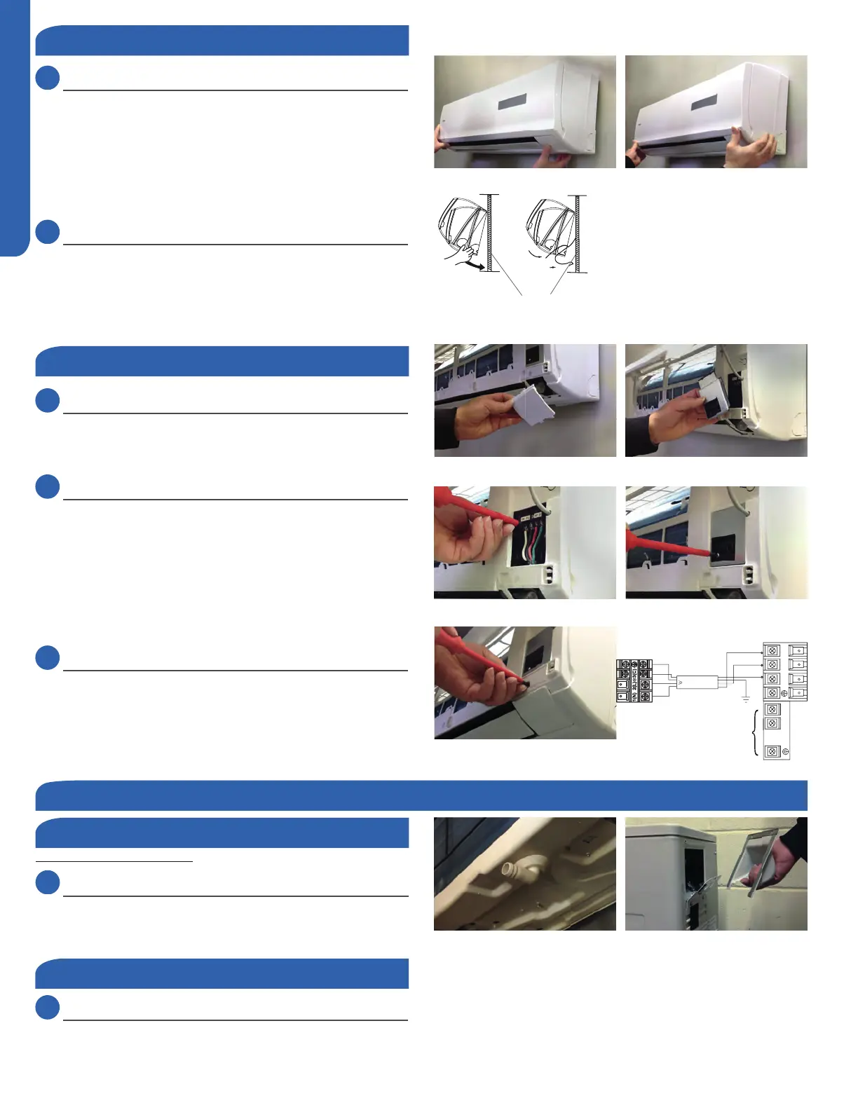
Step 3 - Installation of the Outdoor Unit
Attaching Drain Elbow to Outdoor Unit
3.2
Step - 3.2
Electrical Connections for the Outdoor Unit
 Loading...