Service Manual
Model No.:
- 13 -
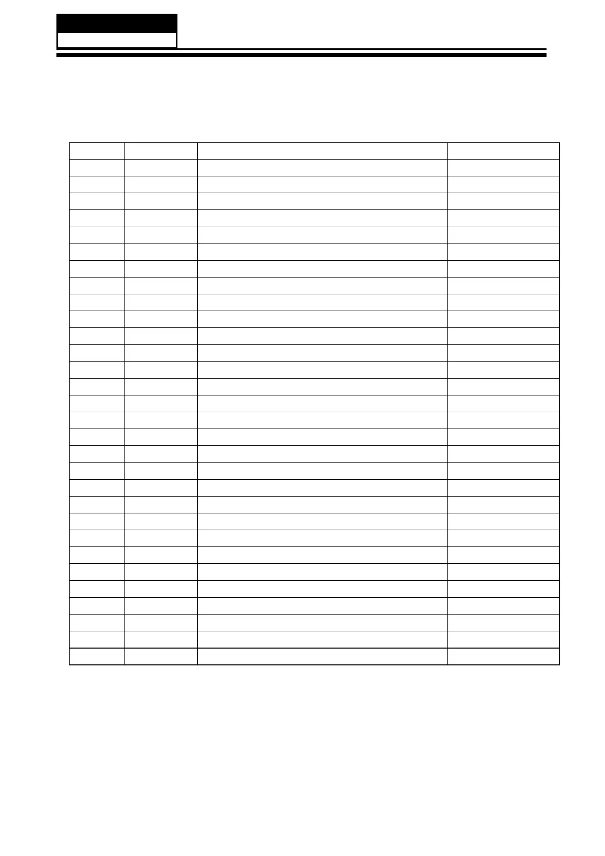
3-5 Interface Connections
Pin No.
Symbol
Description
Note
1
NC
No Connection
(2)
2
NC
No Connection
(2)
3
NC
No Connection
(2)
4
GND
Ground
5
RX0
-
Negative transmission data of pixel 0
6
RX0+
Positive transmission data of pixel 0
7
GND
Ground
8
RX1
-
Negative transmission data of pixel 1
9
RX1+
Positive transmission data of pixel 1
10
GND
Ground
11
RX2
-
Negative transmission data of pixel 2
12
RX2+
Positive transmission data of pixel 2
13
GND
Ground
14
RXCLK
-
Negative of clock
15
RXCLK+
Positive of clock
16
GND
Groun
d
17
RX3
-
Negative transmission data of pixel 3
18
RX3+
Positive transmission data of pixel 3
19
GND
Ground
20
NC
No Connection
(2)
21
SELLVDS
Select LVDS data format
(3)
22
NC
No Connection
(2)
23
GND
Ground
24
GND
Ground
2
5
GND
Ground
26
VCC
Power supply: +5V
27
VCC
Power supply: +5V
28
VCC
Power supply: +5V
29
VCC
Power supply: +5V
30
VCC
Power supply: +5V
Note (1) Connector part no.: P
-
TWO 196108
-
30041 (1.0mm FFC) or compatible
Note (2) Reserved for CMO inte
rnal use, please leave it open
Note (3) Low: JEIDA data format. High/open: VESA data format.
Note (4) Logic level voltage definition: Low: 0V, High: 3.3V

 Loading...