215
Failure code
Outdoor
digital
display tube:
119-1, 2
Indoor wired
controller77
Indoor unit LED status
LED5 Failure description:
Current detecting circuit abnormal of com-
pressor module
20 times
Outdoor unit LED status
LED1 LED2
Normal Normal
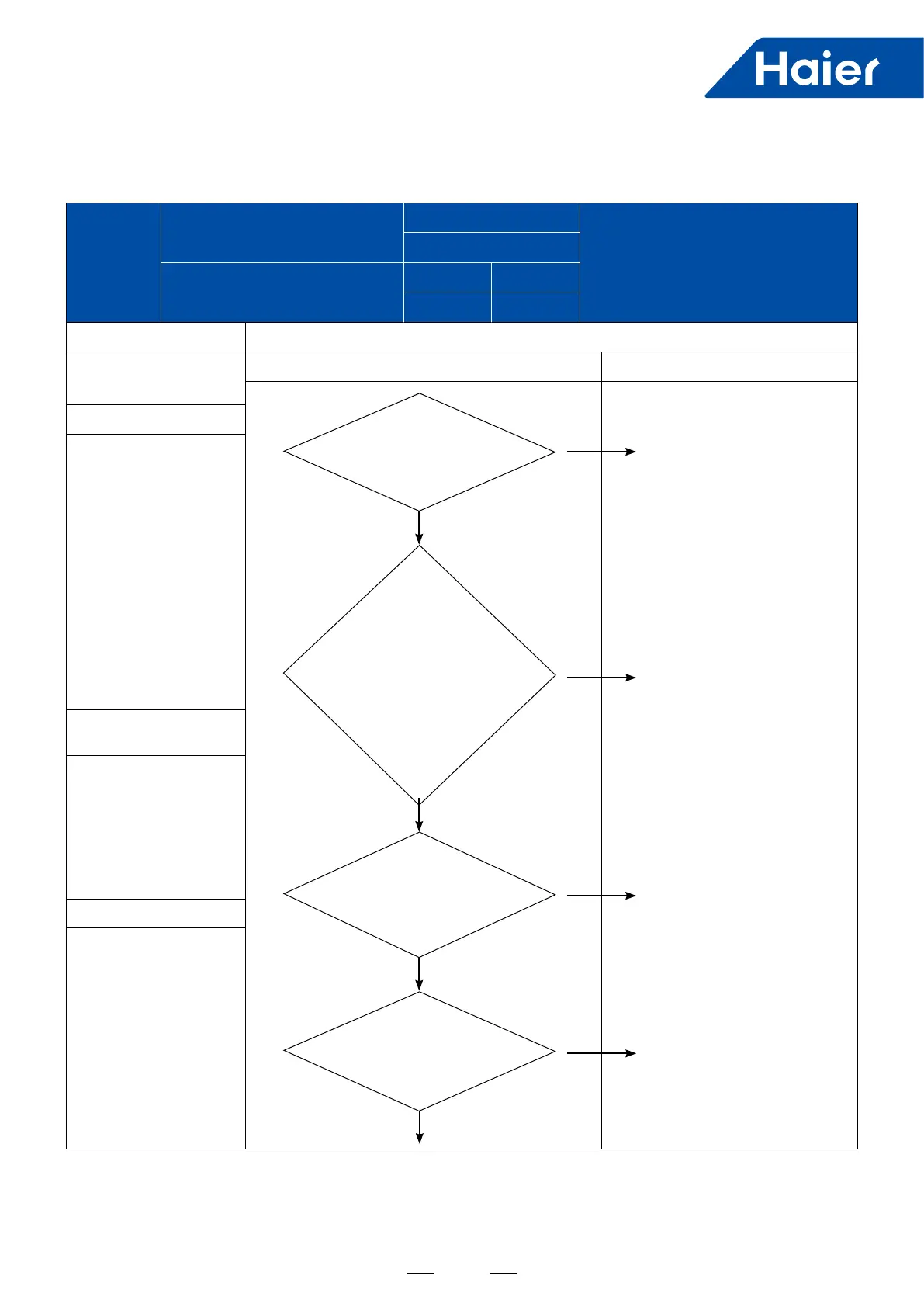
1. Model Failure diagnosis and troubleshooting
MRV 5-RC series
Diagnosis Troubleshooting
2. Abnormity detection method
◆
Check if the current
sensor is reversely
connected and U and W is in
reverse direction.
◆
Check if the current
sensor is in reverse
direction. (the arrow
on sensor points at the
compressor)
◆
Check if the inverter
board is well.
◆
Check if the current
sensor is well.
3. Abnormity conrmation
conditions
The current detection sensor
of inverter control board
is in abnormal conditions,
disconnected or connected
incorrectly.
4. Possible causes
◆
The inverter board and
current sensor is anti-
connected or the current
sensor is in incorrect
direction.
◆
The inverter board or
current sensor is damaged.
Check if there is audible sound
when the compressor starts
before the 119 failure alarm.
(Note: the duration is about 1s.)
After power supply and
upon compressor start, test
the DC voltage between the
second pin (black, earth wire)
and third pin (brown, signal
wire) of the wiring harness
terminal of the two current
sensors, confirm if the signal
voltage is between
1V and 5V?
Conrm if the wiring harness
between inverter control
board CN10 and module
driver board CNDR15V1 is
reliably connected?
Confirm if the wiring harness
between inverter control board
CN9 and module driver board
CNDR1 is reliably connected?
Replace the current sensor
with abnormal signal voltage.
Replace the inverter control
board with abnormal current
detection loop.
Correct the wrong
connection.
Correct the wrong connection.
Y
Y
Y
N
N
N
N
To be continued
Continued
 Loading...