57
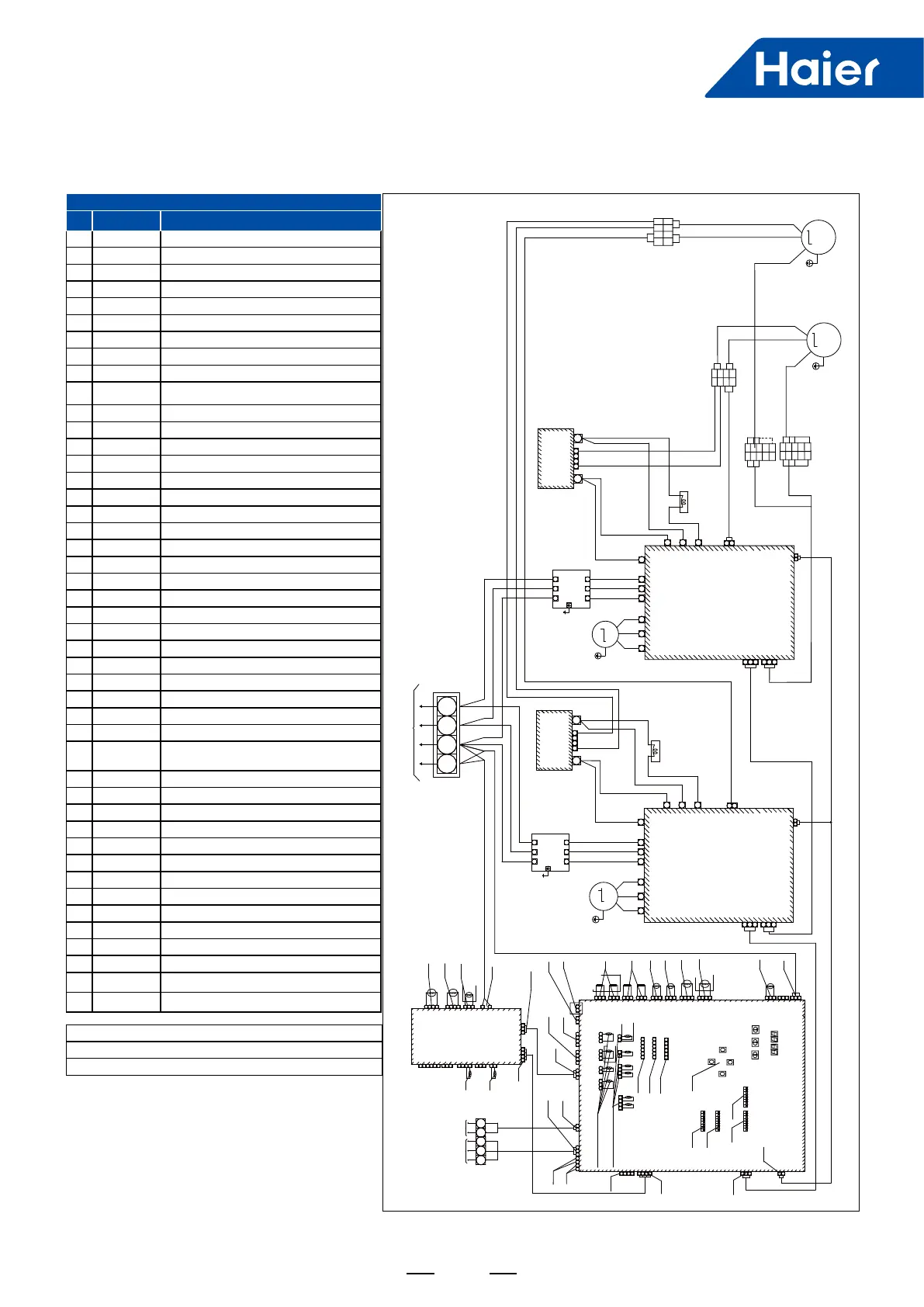
Description of the Main-board Port denition
No. Port Port description
1 L/N/G AC Power Input
2 SV3 Liquid Jetting to compressor 1
3 SV10 Drain the oil from compressor 2
4 SV9 Drain the oil from compressor 1
5 SV1 Balance pressure(Load-OFF)
6 4WV Hot and cold switching
7 HEAT1 Heating band of compressor 1
8 HEAT2 Heating band of compressor 2
9 HPS2 High pressure switch of compressor 2
10 HPS1 High pressure switch of compressor 1
11 Ps Low pressure sensor
12 Pd High pressure sensor
13 Td1 Exhaust temperature of compressor1
14 Td2 Exhaust temperature of compressor2
15 Tdef1 Detect the defrosting temp
16 Tao Ambient temperature
17 Toil2 Detect the oil temp. of compressor 2
18 Toil1 Detect the oil temp. of compressor 1
19 Toci1/Ts Detect SH temp. in heating
20 LEVA1 SH control in heating
21 LEVA2 SH control in heating
22 DC12V Output DC12V
23 BT Output DC5V/Communication
24 P/Q Indoor/outdoor unit com. port
25 A/B/C Outdoor unit com. port
26 Bus-B/A Centralized control port
27 Stop Emergency stop port
28 ZIGBEE Wireless module com. port
29 INV-COM INV module com. port
30 Low Power Low standby power consumption
31 BM1
Outdoor and indoor searching
Outdoor address setting
32 BM2 Wireless communication
33 BM3 HP setting of outdoor units
34 BM4 Set the control address
35 SW4/5/6/7 Special function control keys
36 DC12V Input DC12V
37 L/N AC Power Input
38 SV32 Liquid jetting to compressor 2
39 4WV2 Hot and cold switching
40 4WV3 Hot and cold switching
41 Toci2 Detect SH temp. in heating
42 Tdef2 Detect the defrosting temp
43 Tx Rx Input DC5V/communication
44 Tliqsc/Tsco Detect SH temp. of subcooler
45 LEVB Contral subcooler
Note:
B:Black G:Green W:White BL:Blue R:Red Y:Yellow
The component in the dotted box is used for 16 to 22HP
6. Wiring diagram
L1'
L1
L2'
L2
L3'
L3
N U V W
CN10 CN1CN2CN3 CN7 CN8
CN9
1
2
3
1 2
3
CN21
15V
DCP
P
N
CN4
CN5
CN6
INV Module 1
COMP1
W
V
U
Power:3N~,380V,50/60Hz
L1
L2 L3
N
R S T
Reactor 1
1 2
3
1 2
3
1 2
3
1 2
3 4
SV10
CN8 W
1 2
3 4
1
2
3
1 2
3
1 2
3
1 2
3
1 2
3
1 2
3
12 12
6 5 4 3 2 1
6 5 4 3 2 1
CN20 LEVA1 R
CN21 LEVA2 R
4 3 2 1 4 3 2 1
2
1
2 1
Fuse
T5.0A-250VAC
1 2 3 4
CN18
1
1
2
2
3
CN46
P Q
CN17
A B C
2 13
2 13
Toci1 Ts
4
3
2 13
2 1
Main board
Q
P
A
B
C
1
2
3 4
1
2
3
CN19 W
INV-COM
2 1
Toil1Toil2
CN30
CN34
CN35 Td1
CN37 Td2
CN40 Tdef1
CN38 Tao
CN44
Indoor
Unit
Outdoor
Units
SW1
SW2
SW3
SMG1
SMG2
Digital tube
display
START
DOWN
STOP
UP
Rotate the
dial pad
BM1
ON
SW4
SW7
SW5
SW6
BM4
ON
BM3
ON
N R S T U V W
CN10 CN1CN2CN3 CN7 CN8 CN9
1
2 3
1
2 3
DCP
P
N
CN4
CN5
CN6
INV Module 2
L1' L2' L3'
Filter
Board 2
L1 L2 L3
COMP2
W
V
U
Reactor2
+
-
41
Capacitor
Board 2
+
-
41
M
M
1 2
1 2
15V
15V
DC
540V
DC
540V
DC+
DC-
15V
1
4
1
4
1
4
1
4
1
1
2
3
3
2
COM
CN22
COM1
1
1
COM
Fan1
Fan2
White Terminal
White Terminal
Red Terminal
Red Terminal
5
COM
3
2
3
2
5
COM
GND
P
5
2
3
2
3
2
3
3
2
CN21
15V
W
(R)
Communication
line
ZIGBEE
CN24 W
The right side of the dashed line
indicates that the double fan model
has this part; the single fan model
does not have this part.
2
1
2 13
2
1
34
2
1
3
CN6
Tdef2
CN5
Tsci
CN7
Toci2
CN8
Tsuc
6 5 4 3 2 1
CN20
LEVA3
3 24
CN10 W
TX RX
1
1
CN1 N
CN2 L
1 2
3
CN18 R
SV32
CN13 Y
4WV2
CN14 BL
4WV3
2 13
12V
CN39
1 2
3
4
BT
CN25 W
1
2 13
CN9 W
12V
1 2
1 2
1 2
CN41 W
Low Power
IO Board
2 13
Tsco Tliqsc
4
CN28
Communication
line
DC+
DC-
15V
GND
DC+
DC-
15V
GND
DC+
DC-
15V
GND
B
N
B
R W B
R
W
B
P
N
Capacitor
Board 1
P
N
Filter
Board 1
W(R)
R
B
W(R)
R
B
B R W B
R
W
B
R
W
B
BL
SV9
CN9 R
SV1
CN10 R
4WV(1)
CN11 BL
Heat1
CN3 G
Heat1
CN3_1 G
Heat2
CN4 G
Heat2
CN4_1 G
SV3
CN6 W
Fan1
CN5 B
PD R
CN31
PS BL
CN27
HPS1
CN2 R
HPS2
CN1 R
W
(R)
B
N
P
CN13
CN13
6 5 4 3 2 1
CN22 LEVB R
1 2
3 4
1 2
3 4
BM2
CN24
COM2
CN22
COM1
CN24
COM2
CN16
W
N
L
1
3
2
4
5
6
7
8
11
12
20
21
27
28
29
9
10
24
25
26
35
34
33
31
17/18/19/44
13/14/15/16
22
23
30
36
37
38
39
40
41
42
45
32
43
 Loading...