4
6. OPERATION
●
Controls and displays
Please refer to the FM-202 instruction
manual.
CAUTION:
Refrain from inserting foreign objects, the
wrong end of the tip, or incompatible tips into
the process gate. Damage may result.
NOTE:
If the buzzer sounds three times when the
Tip ID number key is inserted into the pro
-
cess gate, there has been a reading error.
Reinsert the Tip ID number key. If the code
bar is torn or damaged the process gate will
not be able to read it.
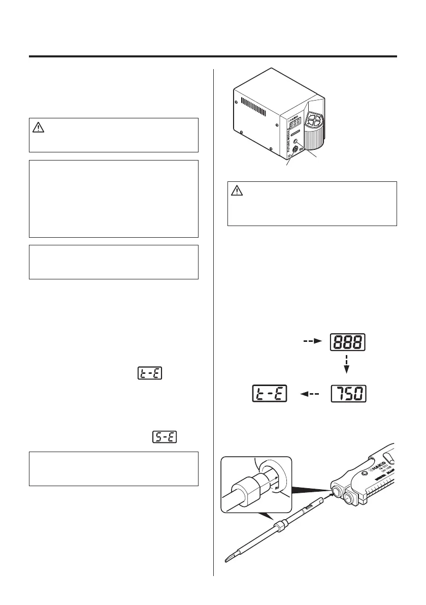
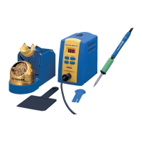
MODEL FM-202
Soldering station
Process gate
Receptacle
NOTE:
This procedure must be followed EVERY
TIME THE TIPS ARE CHANGED.
NOTE:
The tips are a packaged matched set and
must be used together.
There is a flange.
Make sure that the flange will
fit the handle when inserted
into the handpiece
.
●
Displays
1. If tips are in the handpiece, remove
them.
2. Turn the power switch ON.
3. The display will show
and the
LED on the connector will flash.
4. Insert the Tip ID number key into the
process gate until the buzzer sounds
once. ID data are displayed for one
second. The display shows
.
5. Inserting the tip:
Hold the head part of the tip with the
heat resistant pad and insert the tip
into the handpiece. Push until the tip
stops. Repeat for second tip.
CAUTION:
FM-2023 tips do not have a tip ID. Use the
Tip ID number key.
7
7. MAINTENANCE
●
Tip maintenance
Please refer to the FM-202 Instruction manual.
●
Checking Procedure
WARNING:
Unless otherwise directed, carry out these procedures with the power switch OFF and the power
UNPLUGGED.
●
Verify the electrical integrity of
the heater and sensor
1. Check for a broken heater or sensor
Measure the resistance while at room tempera
-
ture(15 to 25°C; 59 to 77°F). It should be 8
Ω
±
10%. If the resistance exceeds these limits, re
-
place the tip.
Measure the resistance across the tip as shown.
●
Check the grounding line 1. Unplug the connection cord from the station.
2. Measure the resistance value between pin 2
and the tip (both tips).
3. If the value exceeds 2
Ω
(at room tem-
perature), perform the tip maintenance de
-
scribed on P.12 of the FM-202 instruction
manual. If the value still does not decrease,
check the connection cord for breakage.
●
Checking the connection cord
for breakage
1. Insert a set of verified tips in both sides of the
handle.
2. Measure the resistance value between two
pins.
Pin 1 - Pin 3 7~9
Ω
Pin 5 - Pin 3 8~10K
Ω
Pin 7 - Pin 4 7~9
Ω
Pin 8 - Pin 4 8~10K
Ω
If the measured value exceeds above values, re
-
place the FM-2023.