25
※ExampleofusingC.O.F.(Changeonthefly)
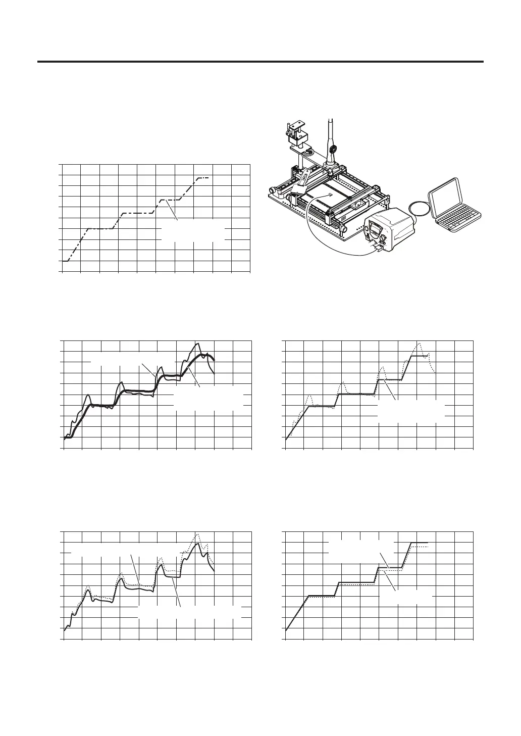
1. Select "PART" in "Sensor selection" (refer to page 11), and attach the thermocouple to the part.
2. Look up the temperature conditions for removing
the part and perform profile settings.
3. When removal is performed according to the settings, the temperature graphs for both the part and
the soldering iron heater will be shown as shown at left below. Select "TOP" in "Sensor selection" and
set the profile from the heater temperature graph.
0
0
30
60
90
120
150
180
210
240
270
300
30 90 120 150 180 210 240 270 30060
[℃]
[sec]
0
0
30
60
90
120
150
180
210
240
270
300
30 90 120 150 180 210 240 270 30060
[℃]
[sec]
0
0
30
60
90
120
150
180
210
240
270
300
30 90 120 150 180 210 240 270 30060
[℃]
[sec]
Part temperature
graph
Heater temperature graph
Parttemperature
profile(setting)
Profile(setting)
basedongraph
0
0
30
60
90
120
150
180
210
240
270
300
30 90 120 150 180 210 240 270 30060
[℃]
[sec]
Initialsetting
4. Prepare a different board and remove the same part using the profile set in step 3. If the actual
measured value is different than the expected temperature, use "C.O.F." to change the set temperature
for each ZONE. (please refer to page 14 for changing settings.)
5. The changed profile can be used to remove parts from boards under the same conditions from then on.
0
0
30
60
90
120
150
180
210
240
270
300
30 90 120 150 180 210 240 270 30060
[℃]
[sec]
Settingchanged
usingC.O.F.
Expectedtemperaturegraph
Actualtemperaturegraph