13
18
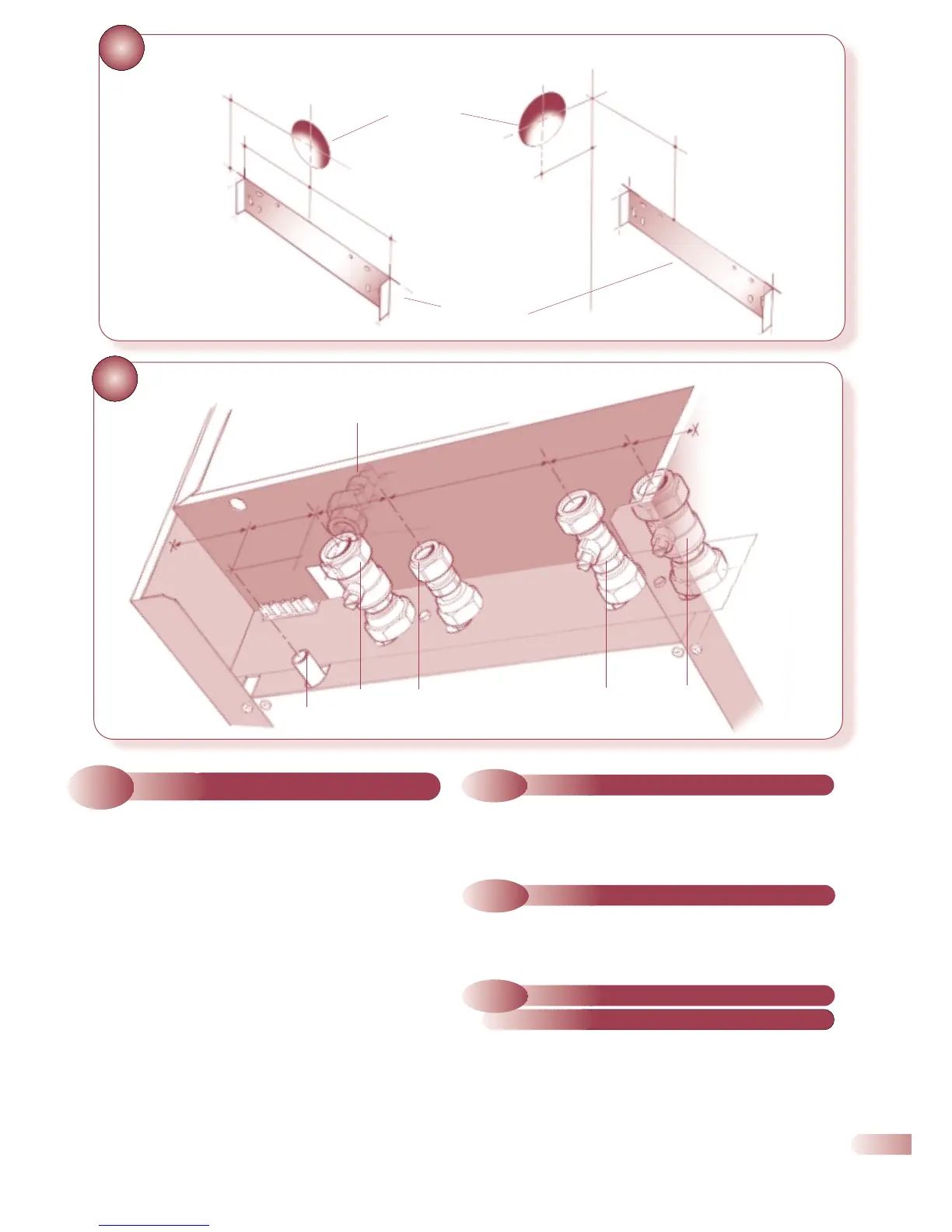
DETERMINING THE POSITION OF THE
AIR/FLUE DUCT HOLE
19
a) Commission the central heating system as described in section
5.1, then proceed to section 4.5.
a) Use a 15mm copper tube or bend to connect to the gas
service cock to a 15mm compression fitting.
a) Lift the boiler into position using the lifting points shown in
Fig. 17. Position the top of the boiler approximately 10mm
above the top of the wall bracket and use the tabs on the wall
bracket to locate the boiler in a horizontal direction, then
carefully lower the boiler ensuring the two locating tabs are
securely engaged (see Fig. 17).
b) Locate and tighten the water and gas valves to the boiler.
(Seals are pre-fitted).
c) Connect the central heating system to the boiler flow and
return using the connections shown in Fig. 19.
d) Connect the mains water supply and outlet to the appropriate
connections as shown in Fig. 19.
4.4
SERVICE CONNECTIONS
4.3
MOUNTING THE BOILER
4.5
GAS CONNECTION
•
PRESSURE
RELIEF
45mm
SERVICE CONNECTIONS (rear view)
a) Connect a suitable discharge pipe to the pressure relief valve
tube. The pipe should be a minimum diameter of 15mm
copper and should avoid any sharp corners or upward pipe
runs where water may be retained. The discharge pipe must
terminate in an area where any discharge will not cause a
hazard but will be noticed.
4.6
PRESSURE RELIEF VALVE
PIPE CONNECTION
•
CENTRAL
HEATING
FLOW
•
DOMESTIC
HOT WATER
OUT
•
GAS COCK
•
MAINS
COLD
WATER IN
•
CENTRAL
HEATING
RETURN
65mm
65mm
133mm
63mm
78mm
18(b) SIDE FLUE
18(a) REAR FLUE
POSITION OF
DUCT HOLE
•
•
POSITION OF
WALLPLATE
•
•
94mm
227.5mm
227.5mm
188mm
94mm