38
SHORT PARTS LIST
SUPPLEMENT
11
Supplementary instructions for flue systems with a vertical outlet.
a) Read the installation requirements and flue specifications
described in section 3.
b) Follow the installation procedure described in section 4 up to
section 4.7 (but making the necessary hole(s) in the ceiling/roof
instead of the wall). Use the following instructions in place of
section 4.7.
c) Measure the vertical distance from the top of the boiler case to
the roof line (Fig. 39). Use this length to calculate the number of
extension ducts required.
d) Starting at the boiler, fit the vertical socket, standard duct and
extensions required. Then fit the adaptors. Ensure that they are in
line (level).
e) Now working from outside fit the balanced flue roof terminal,
ensuring the roof flashing and sealing components are secured to
the roof.
f) Ensure the inner and outer ducts are correctly fitted to the
adaptor.
Note: All the joints should be secured using the self-tapping screws supplied.
9.19
SYSTEM EXPANSION VESSEL
SHORT PARTS LIST
10
In the unlikely event of failure of the expansion vessel diaphragm
it is acceptable to leave the vessel in position and to fit a
replacement vessel (of similar or greater capacity) external to the
appliance but as close as possible to the CH return.
To replace the expansion vessel it is necessary to isolate the
central heating and DHW systems from the appliance, drain the
appliance and remove the appliance from the wall. The vessel can
then be unscrewed and replaced.
9.20
TIME CLOCK
a) Remove the casing front panel and lower the controls fascia
panel as described in section 9.6 step (a).
b) Unplug the four electrical connectors from the back of the
clock.
c) Remove the clock from the panel by releasing four retaining
screws, transfer the wires to the new timer (referring to the
wiring diagrams in section 7 if necessary), and re-assemble in
reverse order.
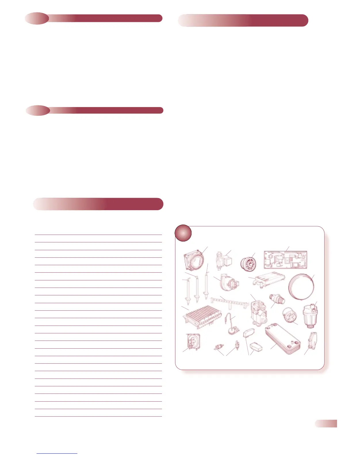
Key G C Part Description No Makers
No. off Pt No.
1 BURNER (Natural gas) 1 700560
2 MANIFOLD SET (Natural gas) 1 700561
3a IGNITION ELECTRODE L/H 1 500620
3b IGNITION ELECTRODE R/H 1 500621
4 DETECTION ELECTRODE 1 500622
5 GAS CONTROL 1 500616
6 PCB 1 500615
7 AIR PRESSURE SWITCH 1 500592
8 FAN ASSEMBLY 1 988416
9 OVERHEAT THERMOSTAT 1 550519
10 THERMISTOR 2 500590
11 MAIN HEAT EXCHANGER 1 450979
12 DHW HEAT EXCHANGER 1
450997 TEN PLATE
13 PRESSURE RELIEF VALVE 1 450987
14 AUTO AIR VENT 1 450908
15 PRESSURE GAUGE 1 450961
16a PUMP 5M (ACE) 1 851214
16b PUMP 6M (ACE HIGH) 1 851213
17 MICROSWITCH ASSEMBLY 2 500593
18 WATER FLOW REGULATOR 1
19 FLOW SWITCH BODY 1 500594
20 EXPANSION VESSEL 1 450999
21 HEATING CLOCK 1 600520
22 ACE RETURN MANIFOLD 1 500554
31
6
20
14
19
12
13
5
2
18
16
21
3a
3b
1
7
10
17
9
4
8
11
15
450985 TWELVE PLATE