5
7
SPECIFICATION FOR VERTICAL FLUE SYSTEMS
Refer to Figures 3 to 7 to determine which option kits are required
before commencing the installation.
Installation instructions for installing the appliance with a standard
flue and straight extension ducts (Fig. 3) are included in the main
text of these instructions (section 4.7). Additional instructions for
flue systems incorporating a vertical outlet (Fig. 7) are given in the
supplements at the rear of this booklet.
b) The standard terminal must always be fitted horizontally. The
vertical terminal must always be used if a vertical outlet is
required.
c) The flue must only terminate in a horizontal or vertical
position. However 90° flue elbows may be used to drop the
height of the flue system by 500mm.
d) The flue system must use either a flanged elbow or a vertical
flue turret socket at the entry/exit to the appliance.
e) All joints must be correctly made and secured in accordance
with the installation instructions.
7(a)
L
•
•
7(b)
b
a
•
•
•
•
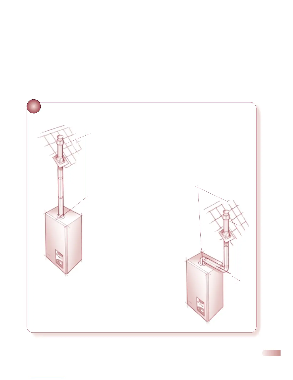
Fig 7(a) Vertical flue assembly with:
Vertical turret socket, standard duct, vertical roof terminal
and extension(s) where required.
‘L’ measured from the top of the boiler casing to the
underside of the air cowl.
Maximum allowable flue length of ‘L’ = Ace 4618mm, Ace
High 3851mm
Fig 7(b) - Offset vertical flue
‘a’ measured from the boiler outlet centre line to the centre
line of the exension elbow
‘b’ measured from the centre line of the extension elbow to
the underside of the air cowl..
Maximum allowable flue length of ‘a’ + ‘b’ = Ace 3084mm,
Ace High 2317mm