EasyManua.ls Logo

Hameg HM 2005 User Manual

Hameg HM 2005
36 pages
To Next Page IconTo Next Page
Page #1 background imageLoading...
Page #1 background image
Oscilloscope
HM 2005
ENGLISH
MANUAL • HANDBUCH • MANUEL
AUTOSET
CT
A/ALT. DEL.TRIG
TR
B
RM
TRS
READ
OUT
PUSH
BOTH
PUSH
LONG
INV.
VAR.
B
ON
OFF
V
t
1
t
1kHz
1MHz
INPUT CH I (HOR. INP.(X))
AC/DC
CAL.
0.2 Vpp
CURSOR
CH I/II
I/II
MENU
max.
250 Vp
1M II
15pF
INPUT CH II
max.
250 Vp
1M II
15pF
TRIG. EXT. INP
max.
100 Vp
(Z)
x1/x10
INV.
x1/x10
200 MHz
ANALOG OSCILLOSCOPE
HM2005
Instruments
TRK
!
CAT
I
!
!
!
GD AC/DC GD
CH I CH II
DEL.POS.
ADD
CHP.
VAR.VAR.
DUAL
X-Y
VOLTS / DIV. VOLTS / DIV. TIME / DIV.
5V 1mV 5V 1mV 0.5s 20ns
TRIG. MODE
TRIG.
ALT
CHI
AC
DC
HF
NR
LF
TVL
TVF
CHII
EXT
Y-POS. I Y-POS. II LEVEL X-POS.
NM
AT
X-
MAG.
POWER
INTENS
EXIT
SAVE
SET
1
FOCUS
9
RECALL
A
RO
6
3
-
K
3
0
4
-
0
0
4
0
/
0
0
5
5
BWL
BW
LIMIT
VAR
VAR
TR
NM
H
O
VAR
x
1
0
T sm005:BD 5RS sn001:t
CH1:=100mV CH2 :~100mV CHP
Question and Answer IconNeed help?

Do you have a question about the Hameg HM 2005 and is the answer not in the manual?

Hameg HM 2005 Specifications

General IconGeneral
TypeOscilloscope
Bandwidth20 MHz
Channels2
Vertical Sensitivity5 mV/div to 20 V/div
Trigger ModesAuto, Normal, Single
Max Input Voltage400 V (DC + AC peak)
Input Impedance1 MΩ
DisplayCRT
Power Supply100-240 V AC

Summary

HM2005 Specifications

Vertical Deflection Specifications

Defines operating modes, frequency range, rise time, deflection coefficients.

Input and Triggering Specifications

Details input impedance, coupling, delay line, and trigger functions.

Horizontal Deflection Specifications

Covers time base, X-magnifier, and holdoff settings.

Important Hints and Safety

Safety and Operating Conditions

Crucial safety requirements and intended use.

Basics of Signal Voltage

Voltage Measurement Principles

Explains RMS, peak values, and amplitude measurement.

Signal Voltage and Time Measurements

Signal Connection and Measurement

Connecting Test Signals and Probes

Guidance on signal connection, AUTOSET, and probe adjustment.

Controls and Readout: Introduction

Controls and Readout: Triggering and Channel I

Triggering Controls (Slope, X-POS, X-MAG, TRIG. MODE)

Manages trigger settings and horizontal expansion.

Channel I Controls (VOLTS/DIV, CHI-VAR)

Sets vertical sensitivity and mode for Channel I.

Controls and Readout: Channel I and Trigger

Trigger and Channel I Controls (LEVEL, TR, VOLTS/DIV, CHI-VAR)

Adjusts trigger level, indicator, and Channel I settings.

Controls and Readout: Channel II and Modes

Channel II and Mode Selection (VOLTS/DIV, CH II-VAR, DUAL-XY, TRIG-ALT)

Controls for Channel II, mode selection, and alternate triggering.

Controls and Readout: Time Base and Trigger

Time Base and Trigger Controls (TIME/DIV, DEL.POS-HO, TRIG. MODE)

Manages time base, holdoff, and trigger coupling.

Controls and Readout: Time Base Modes

Controls and Readout: Input and Trigger

Controls and Readout: Menu and Cursors

Menu System

Menu Navigation (MAIN MENU, TEST & CALIBRATE, SETUP)

Navigates through instrument menus and submenus.

Initial Setup and Calibration

Initial Operation and Probe Adjustment

Guides initial operation and probe adjustment.

Operating Modes: Vertical Amplifiers

Triggering and Time Base

Triggering and Time Base: Modes and Settings

Triggering and Time Base: Advanced Settings

AUTOSET Function

AUTOSET Operation and Settings

Details AUTOSET function and its automatic settings.

Component Tester: Component Analysis

Instrument Adjustments and Interface

Front Panel Overview

Front Panel Controls Diagram

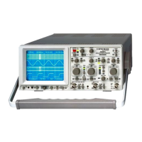
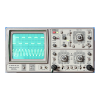
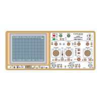
Labeled diagram of all front panel controls.

Related product manuals