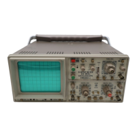
Do you have a question about the Hameg HM303-6 and is the answer not in the manual?
Recommendations for using screened data cables to maintain EMC compliance.
Guidelines for signal cables, emphasizing length and screening for EMC.
Explains how RF fields can affect the oscilloscope's performance.
Description of the YP board's functions, including input, amplifier, and trigger stages.
Description of the trigger signal processing stages on the YP board.
Description of the XY board's functions, including CT, Y Final Amplifier, and X deflection.
Description of the TB board's functions, including sync amp, LF filter, and sawtooth generator.
Description of the CR board's functions, including focus and astigmatism controls.
Description of the CC board's functions, including the calibrator signal.
Explanation of the component tester's oscillator and signal generation.
Function of the FC board, which controls instrument operation via switches and potentiometers.
Description of the PS board, including power supply and high voltage generator.
Procedure for removing and replacing the PS board.
Procedure for removing and replacing the FC board.
Procedure for removing and replacing the CC board.
Procedure for removing and replacing the YP board.
Procedure for removing and replacing the XY board.
Procedure for removing and replacing the TB board.
Procedure for removing and replacing the CR board.
Essential safety advice before performing troubleshooting procedures.
Step-by-step guide on how to safely open the oscilloscope case.
Initial checks and voltage measurements to perform before deeper troubleshooting.
Examples and steps to diagnose errors based on instrument behavior.
List of test equipment needed for performance verification.
Standard oscilloscope settings to apply before starting performance checks.
Verification of trace rotation, CRT intensity, focus, astigmatism, and signal path integrity.
Verification of Y accuracy, square wave response, and balance for CH I/II.
Procedures for checking time base accuracy and X-magnification.
Verification of trigger sensitivity, bandwidth, video, and external trigger functions.
Critical warnings regarding high voltage and qualified personnel for service.
List of necessary test equipment for performing adjustments.
Important notes and basic settings before starting adjustment procedures.
Procedures for adjusting power supply voltages: +146V, +175V, +12V, -6V.
Adjustments for CRT intensity, focus, astigmatism, and Y plate voltage.
Adjustments for Y-gain, balance, and attenuator compensation for CH I/II.
Adjustments for sawtooth start, time base accuracy, and trigger symmetry.
Adjustments for X-magnification, linearity, XY gain, and bandwidth.
| Type | Oscilloscope |
|---|---|
| Bandwidth | 30 MHz |
| Channels | 2 |
| Sample Rate | 100 MS/s |
| Trigger Modes | Auto, Normal, Single |
| Trigger Source | CH1, CH2, Line, Ext |
| Display | CRT |
| Input Impedance | 1 MΩ |
| Power Supply | 100-240 V AC, 50/60 Hz |