Do you have a question about the Hameg HM 103 and is the answer not in the manual?
Details the vertical deflection parameters including bandwidth, sensitivity, and accuracy.
Details the timebase specifications, including sweep rates, accuracy, and trigger system.
Details the horizontal deflection specifications, including bandwidth and input.
Specifies the capabilities and parameters of the built-in component tester.
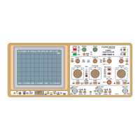
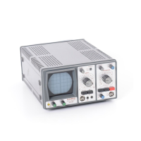
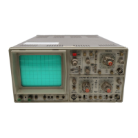
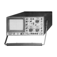
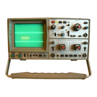
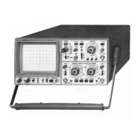
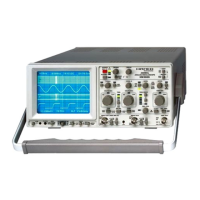
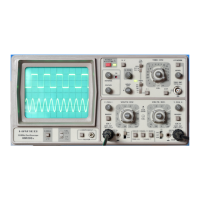
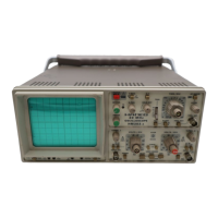
A brief description of the oscilloscope's capabilities and features.
Visual examples of test patterns for component testing.
Overview of the HM103's ease of use, integrated circuits, and front panel arrangement.
Details on the product warranty period, terms, and service.
Safety requirements and precautions for operating the instrument according to standards.
Instructions for using the tilt handle for positioning the oscilloscope.
Steps for initial setup, voltage check, and powering on the instrument for the first time.
Procedure to adjust the vertical amplifier's DC balance for accurate baseline.
Procedure for compensating attenuator probes to match the oscilloscope's input.
Guidance on signal types, bandwidth limitations, and triggering for various waveforms.
Method for performing accurate amplitude measurements using peak-to-peak values.
How to perform time measurements by multiplying horizontal distance by time coefficient.
Instructions on how to connect external test signals using appropriate cables and probes.
Setting up triggering modes and timebase for stable and accurate signal display.
How to use the oscilloscope in X-Y mode for phase comparison and Lissajous figures.
How to use the built-in component tester for checking electronic components.
Quick guide for initial setup, voltage check, and powering on the instrument.
Explanation of automatic and normal triggering modes, and slope selection.
Steps for connecting signals, probe compensation, and performing measurements.
Brief guide on using the component tester and performing in-circuit tests.
Overview of the oscilloscope's front panel layout, controls, and connectors.
Introduction to test procedures, required qualifications, and initial setup.
Procedures for testing CRT brightness, focus, linearity, and raster distortions.
Procedure for checking and adjusting the astigmatism of the CRT display.
Testing vertical amplifier symmetry and measuring baseline drift over time.
Steps for calibrating the vertical amplifier using the built-in calibrator signal.
Checking the transient response and delay distortion correction of the vertical amplifier.
Verifying the trigger circuit's performance, sensitivity, and edge selection.
Procedures for checking timebase accuracy, linearity, and frequency ranges.
Testing the functionality of the X-Y mode for signal comparison.
Testing the functionality and output patterns of the component tester.
Adjusting trace rotation for proper alignment using the TR potentiometer.
Checking instrument stability and display variations under power voltage fluctuations.
Guidelines for technicians on performing adjustments and repairs on the HM103.
Instructions for changing the instrument's mains voltage setting and fuse replacement.
Steps for safely removing the instrument's rear cover for access to internal components.
Procedures for measuring and checking DC and AC operating voltages within the instrument.
Adjusting brightness controls.
Adjusting astigmatism correction potentiometer for optimal display sharpness.
Information on setting the internal trigger threshold and potential issues.
Guidance for diagnosing and fixing instrument faults, including visual inspection.
Checking CRT vertical deflection plate voltages for troubleshooting.
Checking CRT horizontal deflection plate voltages for troubleshooting.
Troubleshooting steps related to the CRT circuit and potential faults.
Troubleshooting steps related to the power supply section and its output voltages.
Guidelines for selecting and replacing components and parts within the instrument.
Overview of general adjustment procedures requiring specific instruments and expertise.
Overview of the oscilloscope's internal functional blocks and signal flow.
Identification of common transistors and ICs, including their terminals and types.
Key for identifying resistor types, tolerances, and power ratings.
Legend for wire color coding used within the instrument for identification.
| Brand | Hameg |
|---|---|
| Model | HM 103 |
| Category | Test Equipment |
| Language | English |