Do you have a question about the Hameg HM205-2 and is the answer not in the manual?
Defines operating modes, frequency range, risetime, deflection coefficients, input impedance, and Y output.
Covers automatic, normal, level control, slope, coupling, and TV sync separator features for triggering.
Details time coefficients, X-expansion, holdoff-time, and X-Y phase shift for horizontal deflection.
Describes operating modes, memory size, sampling rate, resolution, and output options for digital storage.
Explains test voltage, current, frequency, and grounding for the component tester.
Provides details on CRT, calibrator, line voltages, power consumption, weight, and dimensions.
Lists supplied accessories: switchable probes, trimming tool, line cord, and manual.
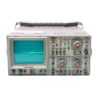
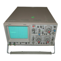
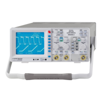
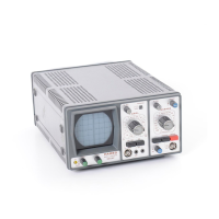
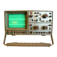
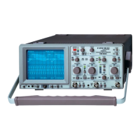
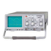
Overview of the HM205-2, initial checks, tilt handle usage, and basic operation.
Details safety requirements, protective conductor use, and warnings regarding high voltage and hazards.
Explains guarantee conditions, maintenance guidelines, cleaning, and recommended test equipment.
Explains how to change the mains/line voltage setting and fuse replacement.
Discusses signal types, frequency limits, AC/DC coupling, and amplitude measurement techniques.
Guides on reference line, time measurements, risetime/falltime, and signal connection.
Step-by-step guide for initial power-on, probe compensation, and trace adjustment.
Details automatic, normal, slope, coupling, line, video, and external triggering modes.
Explains using HOLD OFF to stabilize display on complex signals or aperiodic pulse trains.
Introduces the CT, its basic operation, controls, and connecting test leads.
Guides for performing tests, interpreting patterns for resistors, capacitors, semiconductors.
Details testing diodes, in-circuit components, and transistors (NPN/PNP).
Identifies controls for storage: STOR., HOLD I/II, SINGLE, RESET, DOT J.
Details vertical/horizontal resolution, max frequency, and single channel display.
Describes the rear panel BNC output providing a sample of CH.I or CH.II signals.
Steps for powering on, setting controls, amplifier modes, and triggering.
Brief overview of storage mode, measurement setup, and component tester usage.
Detailed description of front panel elements from POWER to CALIBRATOR.
Detailed description of front panel elements from COMPONENT TESTER to DOT J.
Guides for regular checks, CRT, astigmatism, and vertical amplifier symmetry.
Covers vertical amplifier calibration, transmission performance, and operating mode tests.
Checks timebase ranges, component tester, trace alignment, mains stability, and Y-output.
Guidelines for technicians, case removal, safety precautions, and voltage checks.
Details astigmatism, trigger threshold, general troubleshooting, and CRT voltage checks.
Guidance on replacing parts, ordering, and replacing the power transformer.
High voltage warning, service guidelines, and table of calibration steps.
Covers +12V supply, CRT intensity, trace rotation, and channel balance adjustments.
Details gain, HF adjustments, attenuator compensation, trigger symmetry, and DC triggering.
Covers X-magnification, timebase calibration, X-Y gain, and specific trigger adjustments.
Tests for trigger filter, bandwidth, line/external trigger, and calibrator output.
Testing Dual/Chop modes, component tester Y-position, and video trigger settings.
Adjusting VR4 for Y-gain and VR5 for Y-output symmetry in storage.
Adjusting VR1, VR3 for Y-position and VR2100 for Y-out sensitivity.
Referencing analog section for CH I/II Y-gain adjustments in storage mode.
| Type | Oscilloscope |
|---|---|
| Bandwidth | 20 MHz |
| Channels | 2 |
| Sample Rate | 100 MS/s |
| Trigger Modes | Auto, Normal, Single |
| Trigger Source | CH1, CH2, Line, Ext |
| Max Input Voltage | 400 V (DC + AC Peak) |
| Input Impedance | 1 MΩ |
| Display | CRT |
| Power Supply | 100-240 VAC, 50/60 Hz |