Do you have a question about the Hameg HM404-2.02 and is the answer not in the manual?
Details compliance with CE directives (EMC, Low-Voltage) and applied harmonized standards.
Explains symbols, safety class, grounding, and operating conditions for safe use.
Covers EMC, power supply, warranty, and maintenance requirements.
Methods for measuring signal voltage amplitudes, including peak-to-peak and RMS.
Procedures for measuring time intervals, periods, and frequencies using the time base.
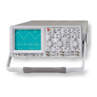
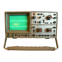
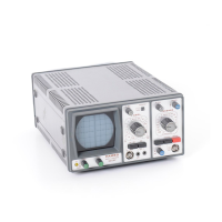
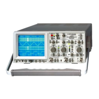
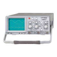
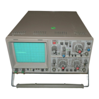
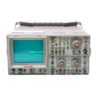
Introduces key controls like POWER, AUTO SET, INTENS, FOCUS, and SAVE/RECALL.
Adjusting vertical trace position (Y-POS I/II) and amplifier settings.
Setting up trigger modes (NM-AT), level, slope, and coupling for stable displays.
Adjusting horizontal sweep speed, position, magnification, and delay functions.
Correcting horizontal trace alignment affected by magnetic fields.
Procedures for matching probes for accurate waveform measurements at 1kHz and 1MHz.
Explains single channel, dual, and ADD modes for Yt display.
Displays signals as X-Y plots, disabling the time base.
Using Lissajous figures to analyze phase differences between signals.
Measuring phase shifts between signals in Yt Dual mode.
Explains the purpose of triggering and basic principles.
How automatic and normal triggering modes function.
Setting trigger slope and signal coupling (AC, DC, HF, LF, TV).
Using TV-L and TV-F modes for stable video signal triggering.
Using mains frequency or triggering two asynchronous signals.
Utilizing an external trigger source for synchronization.
Visual feedback on trigger signal status and level correctness.
Adjusting hold-off time and using delay/after-delay triggering for signal analysis.
Using SEA./DEL. and DEL.TRIG. for signal expansion and specific trigger points.
Automatically configures the oscilloscope for optimal signal display.
Shows the average DC value of the signal during cursor measurements.
Overview of the built-in component tester and its capabilities.
Steps for testing components and interpreting displayed patterns (resistors, capacitors, diodes).
Specifics on testing diodes, Zener diodes, and semiconductor characteristics.
Testing transistors, including in-circuit tests, and understanding patterns.
Information on calibration and adjustments related to component testing.
Safety warnings for RS232 use and how to operate via PC.
Specifications for the serial cable and communication protocol settings.
| Brand | Hameg |
|---|---|
| Model | HM404-2.02 |
| Category | Test Equipment |
| Language | English |