21
Subject to change without notice
Replacement of modules
Module changed Readjustment/Check necessary, step:
ATT-R 3.2.6, 3.2.8, 2.2.11
ATT-T 3.2.6, 3.2.10
RF-Box 3.2.6, 3.2.8, 2.2.11
IF-Unit 3.2.6, 3.2.8, 3.2.7, 3.2.5
CPU-Board 3.2.2 – 3.2.6, 3.2.8, 3.2.9
XYZ-Board 3.2.2, 3.2.3
PS-Board 3.2.1 – 3.2.3
KEY-Board 3.2.2 – 3.2.4, 3.2.8, 3.2.10
Interface None
CRT module 3.2.2 – 3.2.4
Jacks/Covers None
Changing mechanical parts like front cover or input connectors
will not affect adjustment of the HM5014-2
5.1 Opening the instrument
Always make sure that when working on the instrument the
mains connection is removed. When working with voltages
present, take extra care not to touch exposed connections
and components.
5.1.1 Remove the handle
The handle can be removed by pulling it out in position “F“ as
shown in fi gure 5-1 and fi gure 5-2.
Figure 5-1: Removing Handle
A
B
C
D
E
T
F
Figure 5-2: Removing Position
5. Module Replacement
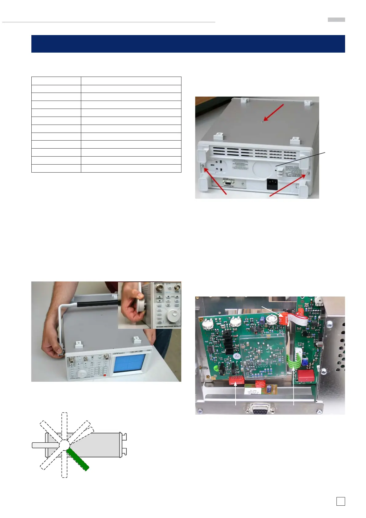
5.1.2 Remove the Rear Cover
Unscrew the two hexagon cap nuts as shown in fi gure 5-3. Use
tool A7 (see paragraph 1.3, table 1-2). Remove the rear cover
by pushing it backwards.
Rear Cover
Screw,
fi xing the casing
Figure 5-3: Back-Bottom View of HM5014-2 without handle
5.1.3 Remove the casing
Unscrew the crosshead screw as shown in fi gure 5-3 Use
tool A4 (see paragraph 1.3, table 1-2). Remove the casing by
pushing it backwards.
5.2 Replacement of XYZ-Board
Turn the HM5014-2 to the rear side. Make absolutely sure the
unit is not connected to mains! See Fig. 5-4 showing the cable
locations.
RiC10
RiC11 WiC2
Figure 5-4: Location of XYZ module, cables
5.2.1 Removal of XYZ-Board
Remove the cables RiC10, WiC2 and RiC11 from the connectors
on the XYZ-board. The cables are shown in Fig. 5-4. Then gent-
ly pull the XYZ-board away from the CRT socket, after about 6
mm it will come loose.
5.2.2 Installing of XYZ-Board
Set the new XYZ module on the CRT socket so that the nose
on the CRT socket fi ts into the notch on the socket on XYZ-mo-
5. Module Replacement
 Loading...


