24
Subject to change without notice
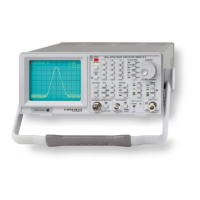
M1
M2
M4
M3
Figure 5-10: Location of the screws of the RF unit
Gently pull the RF box backward until the connector to the RF
ATT is disconnected, then loosen the remaining cable RiC4 and
the coaxial connection to the TG module (CiC3). Lift the RF box
out of the HM5014-2 (See Fig. 5-9).
5.9.2 Installing of RF-Box
Put the new RF box so that RiC4 can be connected, feed the 2
coaxial cables through the appropriate holes in the chassis, and
connect them to the 2 SMB jacks on CPU board, CiC 4 in front and
CiC8 the second from the front. Gently insert into the mounting
bay and fi x cable RiC4 and the coaxial connection to the TG module
(CiC3). Then insert the RF box into its position by sliding it on the
SMB connector of the RF ATT box. Turn the HM5014-2 into its nor-
mal position. Fix the RF box in place using 4 countersunk screws
and make sure it is pushed against the RF ATT while tightening
the screws. Reinstall the IF unit (see paragraph 5.4). Take the
HM5014-2 into operation (ref. to paragraph 5.18)
5.10 Replacement of RF ATT module
The replacement of the RF ATT module requires that IF unit (see
5.4) and RF box (see 5.9) are removed prior to the replacement
of the RF ATT module.
5.10.1 Removal of RF ATT module
Turn the HM5014-2 upside down. Remove the SMB connector of
SiC1 from the RF ATT module (outside). Loosen the 2 crosshead
screws holding the RF ATT module in place and gently remove
the RF ATT module, disconnect WiC6 from RF ATT module.
5.10.2 Installing of RF ATT module
Insert the new RF ATT into its space and insert WiC6 connector.
Put the RF ATT module in its place and fi x it with the 2 cross-
head screws. Place the SMB connector of SiC1 on the SMB jack.
Insert RF box and IF-unit (see paragraph 5.9 and 5.4). Take the
HM5014-2 into operation (ref. to paragraph 5.18)
5.11 Replacement of KEY board
Prior to replacing the KEY board, the IF unit must be removed (see
paragraph 5.4) as well as the front cover (see paragraph 5.12)
5.11.1 Removal of KEY board
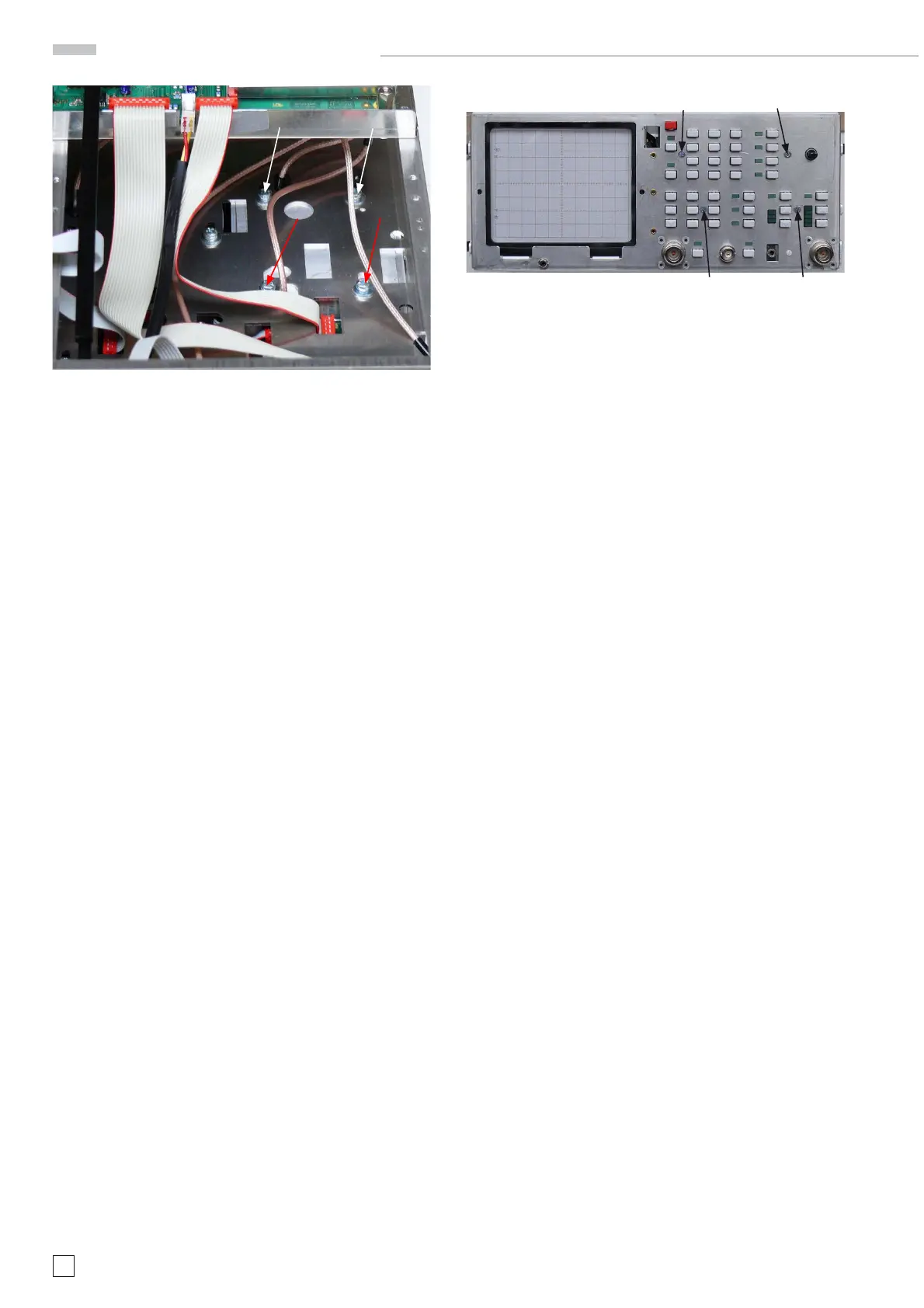
Loosen the 4 countersunk screws that hold the KEY module from
the front side, locations are indicated in the fi gure 5-11.
M4 M3
M1 M2
Figure 5-11: Location of the screws of the KEY board
When loose, remove the connectors of RiC6, RiC2, RiC7 and
WiC5. Remove the KEY board out of the HM5014-2 by lifting it
vertically out of the instrument. Be careful not to damage the
probe power jack.
5.11.2 Installing of KEY board
Carefully insert the new KEY module into the unit from the top,
be careful not to damage the probe power jack, the shaft of the
rotary encoder and the caps of the buttons. Fix the connectors
of RiC6, RiC2, RiC7 and WiC5 to the KEY board. Put the KEY
board in place and fi x it with the 4 countersunk screws shown
in photo (see Fig. 5-11). Inser t the IF unit (see Fig. 5-4). Take the
HM5014-2 into operation (ref. to paragraph 5.18)
5.12 Replacing the front cover
5.12.1 Removal of the the Front Cover
Remove the knob of the rotary encoder, by pulling it forward.
Remove the front panel by releasing the four snap-in noses at
the right and left side of the panel and pulling the panel for-
ward.
5.12.2 Installing the new Front Cover
Push the front cover onto the front chassis. Caution with the
buttons! The four clips of the front cover must snap behind the
fl ange of the front chassis. Press the knob of the rotary enco-
der on the axis of the encoder.
5.13 Replacement of the Rear Cover
5.13.1 Removal of the the Rear Cover
see paragraph 5.1.2
5.13.2 Installing the new Rear Cover
Push rear cover onto the rear chassis. Screw the two hex cap
nuts as shown in fi gure 5-3.
5.14 Replacement of CRT module
5.14.1 Removal of the CRT Module
First remove the CPU board (see paragraph 5.5.1), then remove
the XYZ module (see paragraph 5.2.1). Remove the hex nuts M1
and M2 from the CRT bracket as shown in Fig. 5-12. Use the
jaw wrench size 5.5 mm, tool A9.
5. Module Replacement
 Loading...


