46
Introduction
played. The value should be appr. 280 µH. As shown in Fig.
3.2, the phase angle of an inductor must be in the range
of + 45 to 90°. In order to prove this, leave the automatic
mode by pushing the button „Z-Θ
39
. The phase angle dis-
played will be appr. +70° and depends on the measuring
frequency set.
For comparison: the phase angle of the capacitor meas-
ured before is appr. -87° at 50 Hz.
3.4 Measurement of a resistor
Disconnect the choke and connect the 100 kΩ resistor sup-
plied. As the instrument was previously set manually to the
function Z-Θ, the value of its impedance can be directly
read (appr. 100 kΩ). As decribed on the page before, an
ideal resistor has no capacitive or inductive components.
Hence the phase resp. loss angle of the component con-
nected is close to zero degrees.
The HM8118, upon connection of the resistor, automat-
ically changed the internal equivalent circuit from series
connection SER to parallel connection PAR (LED pushbut-
tons
15
and
16
). If the automatic selection of the equivalent
circuit was chosen (pushbutton AUTO
14
), the LCR meas-
uring bridge will automatically select the equivalent circuit
which, depending on the component connected, is best
suited to yield a precise measurement result. The equiv-
alent circuit represents the measurement circuit. Usually,
components with a low impedance (capacitors, chokes)
will be measured using the series connection equivalent
circuit while components with a high impe-
dance (e.g. resistors) will be measured using the parallel
equivalent circuit.
4 First-Time Ope-
ration
4.1 Connecting the instrument
Prior to connecting the instrument to the mains, check
whether the mains voltage conforms to the mains voltage
range specied on the rear panel. This instrument has a
wide-range power supply and hence requires no manual
setting of the mains voltage.
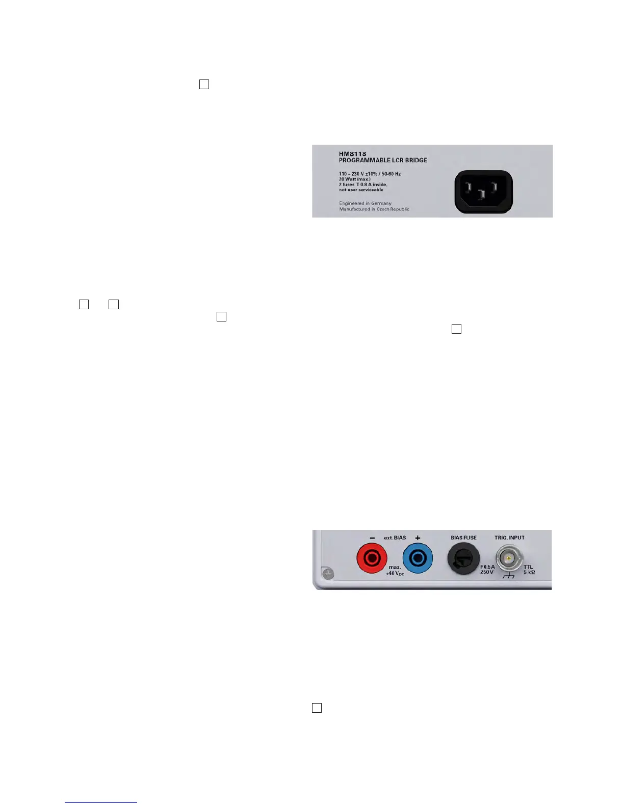
The fuse holder of the BIAS FUSE
45
, i.e. the external BIAS
input, is accessible on the rear panel. Prior to exchanging a
fuse the instrument must be disconnected from the mains.
Then the fuse holder may be removed with a suitable
screw driver, using the slot provided. Afterwards the fuse
can be removed from the holder and exchanged. The hol-
der is spring-loaded and has to be pushed in and turned.
It is prohibited to use „repaired“ fuses or to short-circuit
the fuse. Any damages incurred by such manipulations will
void the warranty. The fuse may only be exchanged by this
type:
Fuse with ceramic body, lled with re extinguishing
material:
Size 6.3 x 32 mm; 400 V
AC
, C; IEC 127, Bl. III; DIN 41 662
(alternatively DIN 41 571, p. 3), (F) 0,5 A
4.2 Turning on the instrument
Prior to operating the instrument for the rst time, ple-
ase be sure to observe the safety instructions mentioned
previously!
The LCR bridge is switched on by using the power switch
1
. Once all keys have briey been illuminated, the bridge
can be operated via keys and the knob on the front pa-
nel. If the keys and the display do not light up, either the
mains voltage is switched off or the internal input line fu-
ses are defective. The current measurement results are
Fig. 4.1: Power Input
Fig. 4.2: Rear panel with fuse

 Loading...


