43
Description of the Operating Elements
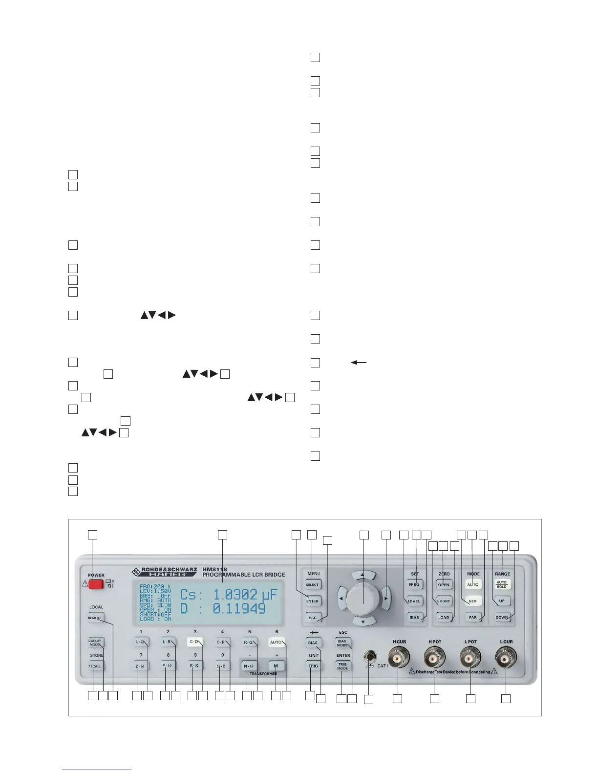
Fig. 2.1: Front panel of HM8118
2 Description of
the Operating
Elements
Front panel of HM8118
1
POWER – Turning on/off the instrument
2
DISPLAY (LCD) – Display of measurement results and
units, ranges, frequencies, level, equivalent circuit,
functions and parameters
MENU
3
SELECT – Opening the submenus SETUP, CORR, SYST
and BIN (only with installed Binning Interface HO118)
4
ENTER – Conrmation of input values
5
ESC – Cancel the menu function
6
Rotary knob (Knob/Pushbutton) – Selection of func-
tions and parameters
7
Arrow buttons – Pushbuttons for parameter
selection
SET
8
FREQ – Setting of the test signal frequency with rotary
knob
6
or arrow buttons
7
9
LEVEL – Setting of the test signal level with rotary knob
6
and cursor position with arrow buttons
7
10
BIAS – Setting of the bias voltage or current with ro-
tary knob
6
and cursor position with arrow buttons
7
ZERO
11
OPEN – Activating the OPEN calibration
12
SHORT – Activating the SHORT calibration
13
LOAD – Activating the LOAD calibration
MODE
14
AUTO – Activating the automatic selection of equiva-
lent circuit
15
SER – Activating the series equivalent circuit
16
PAR – Activating the parallel equivalent circuit
RANGE
17
AUTO/HOLD – Activating the automatic measurement
range (LED lights up) or the range HOLD function
18
UP – Range up
19
DOWN – Range down
Connectors
20
L CUR (BNC socket) – Low Current; signal output for
series measurements (signal generator)
21
L POT (BNC socket) – Low Potential; signal input for pa-
rallel measurement (voltage measurements)
22
H POT (BNC socket) – High Potential; signal input / out-
put for parallel measurements (measurement bridge)
23
H CUR (BNC socket) – High Current; signal input for se-
ries measurements (current measurements)
Instrument functions
24
BIAS MODE/ESC – Activating of internal / external bias
voltage resp. cancelling the editing mode (ESC)
25
TRIG MODE/ENTER – Changing the trigger mode resp.
conrming an input value
26
BIAS / – Activating the bias voltage resp. erasing
the last character of an numeric input
27
TRIG / UNIT – Single trigger in manual trigger mode
resp. selection of a parameter unit
28
AUTO / 6 – Activating the automatic measurement
function resp. entering numeric value 6
29
M / – – Selection of the measurement function „Mutual
Inductance“ resp. parameter input of the character „-“.
30
R-Q / 5 – Selection of the measurement function ‘Resis-
tance‘ R und ‘Quality factor‘ Q resp. entering numeric
value 5
1 2 4 3
5
6 7 9 8 10
12 11 13
15 14 16
18 17 19
22 21
20
24
43
232526
27282930313233343536373839424041

 Loading...


