DATEREV. NAME CHANGES
REVISION
LOCATION:
Document created with version :
CONTRACT N° :
SCHEME
04
L1 Main Panel
BCB Layout
1
User data 2
1
0
Brian
Brian
11/15/2017
10/10/2017
Updated wire colors & AWG
X2
1
1
X21 X7
1
1
1
X13 X4
X5X22
SG E-Stop
Safety
Add
Sensor
Tank
(B) Out
1
1
X3
X15
1
X17
11
X9
11
X16X25
1
1
X8 X26 X12
1
1
X6 X10
(B) In
(A) In
Therm
Room
Demand
HeatFault
(+)
0-10 Vdc
(-)
Sensor
Outdoor
Sensor
External
Cascade
(A) Out
High Limit
& Outlet Sensor
Gas Pressure
Transducer
Flue Sensor
Return Sensor
Fan Pressure
Transducer
Outlet Pressure
Transducer
Blocked Drain
Transducer
Inlet Pressure
Transducer
SW1
L N3
Ignition Transformer
03-11
03-12
03-13
03-14
03-3
03-2
03-3
Optional
3-Way Valve
J15
CN12
Fan
Optional
PWM Pump
03-2
BDB
+-
B/OT A/OT
04-4
04-13
04-4
04-13
04-4
04-13
04-4
04-13
04-6
04-12
04-6
04-12
04-6
04-12
04-6
04-12
Rear Wall Limit SwitchDoor Limit Switch
LWCO
Optional
See LWCO Wire
Diagram For Details
04-4
04-13
18
22Black
22Brown
22Black
18Red
18Red
18Red
22Blue
22Blue
22Brown
22White
18Red
22Green
22Red
22Black
18Black
18White
18Black
18White
18White
18Black
18Black
18White
18Black | White
18Black
18White
18Gr een
22Red
22Green
18Black
22Black
22Green
22Red
22Green
22Black
22Red
18Green
22Blue
22Red
22Black
22Re d | Black
22Re d | Black
22Yellow | Black
22Yellow | Black
22Violet
22Violet
18Yellow
18Yellow
18Yellow
18Yellow
18Black
18Blue | White
18Blue | White
22Grey
22Grey
22Orange
22Oran ge
22Green
22Black
22Red
22White
22Red
18Red
03-3
11
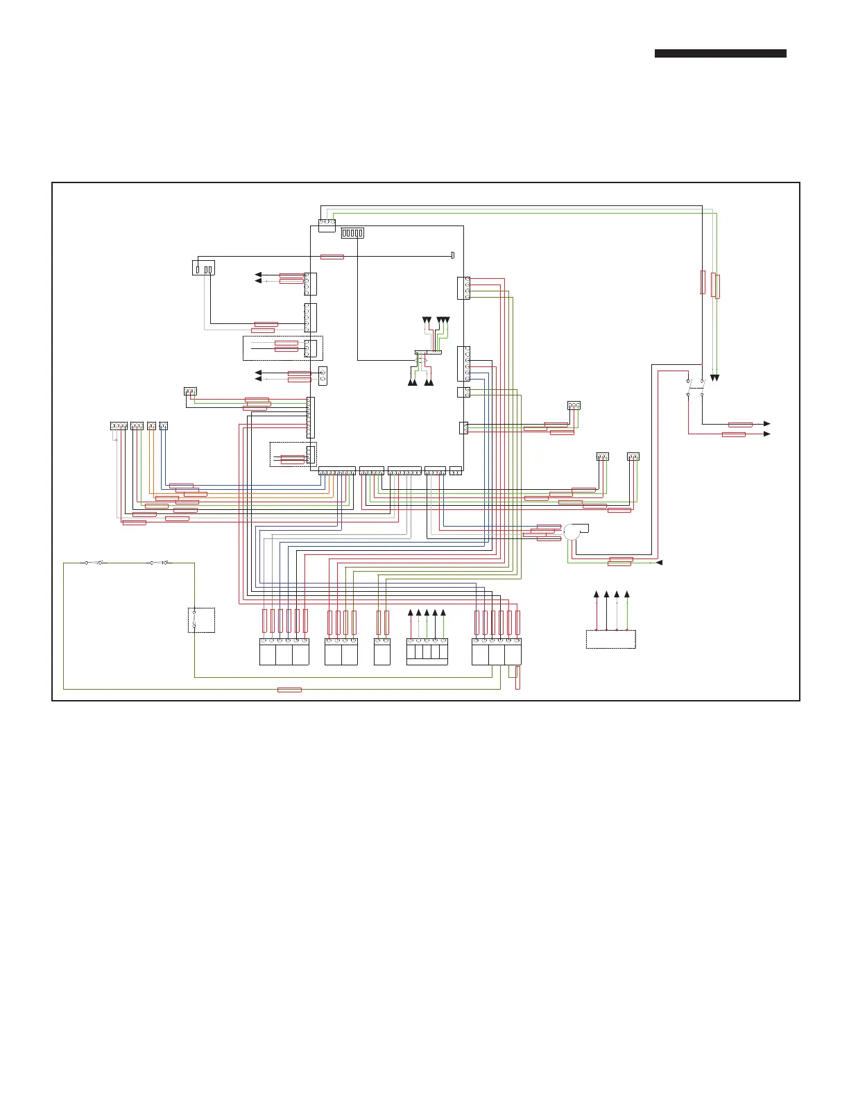
PART 2. ELECTRICAL
B. INTERNAL WIRING CONNECTION (continued)
FIGURE 21 .2 FIELD WIRING CONNECTIONS
A. Outdoor Sensor — outdoor air
sensor, set point will adjust
based on outdoor air temperature
(not needed if 0-10 VDC output is
connected)
B. External Sensor Connection —
system temperature sensor,
senses water temp in a heating
loop.
C. Tank Sensor — Sensor for indirect
or direct DHW. An aquastat may
also be connected here.
D. 0–10 VDC — connect a 0–10
VDC output here to vary set point
temperature.
E. Additional Heat Demand —
dry contacts that will close a
thermostat on an extra heater/
boiler if the boiler is at 100% of
capacity.
F. Fault Service — alarm bell or light
may be connected here to indicate
that the boiler is a hard lockout.
G. Room Thermostat — normally
jumped. A room thermostat may
be connected here to enable/
disable the heater/boiler.
H. Cascade Connection —
communication cables get
connected here and “daisy
chained” to all heaters/boilers in a
cascade. This is polarity sensitive.
I. 3-Way Diverter Valve — Used
in a boiler system with both
Heating and Indirect Hot Water.
J. P2 — Pump for indirect. Used in
a boiler system with both
Heating and Indirect Hot Water.
K. P1 — Wire to primary pump for
boilers and heaters.
L. P3 — Wire to system pump
for boilers.