MOC.YABNOTPMAH
11
.ecnatsissa rehtruf rof 3130-725-778-1 tcatnoc esaelP
Assembly – Attaching the Accessories
9
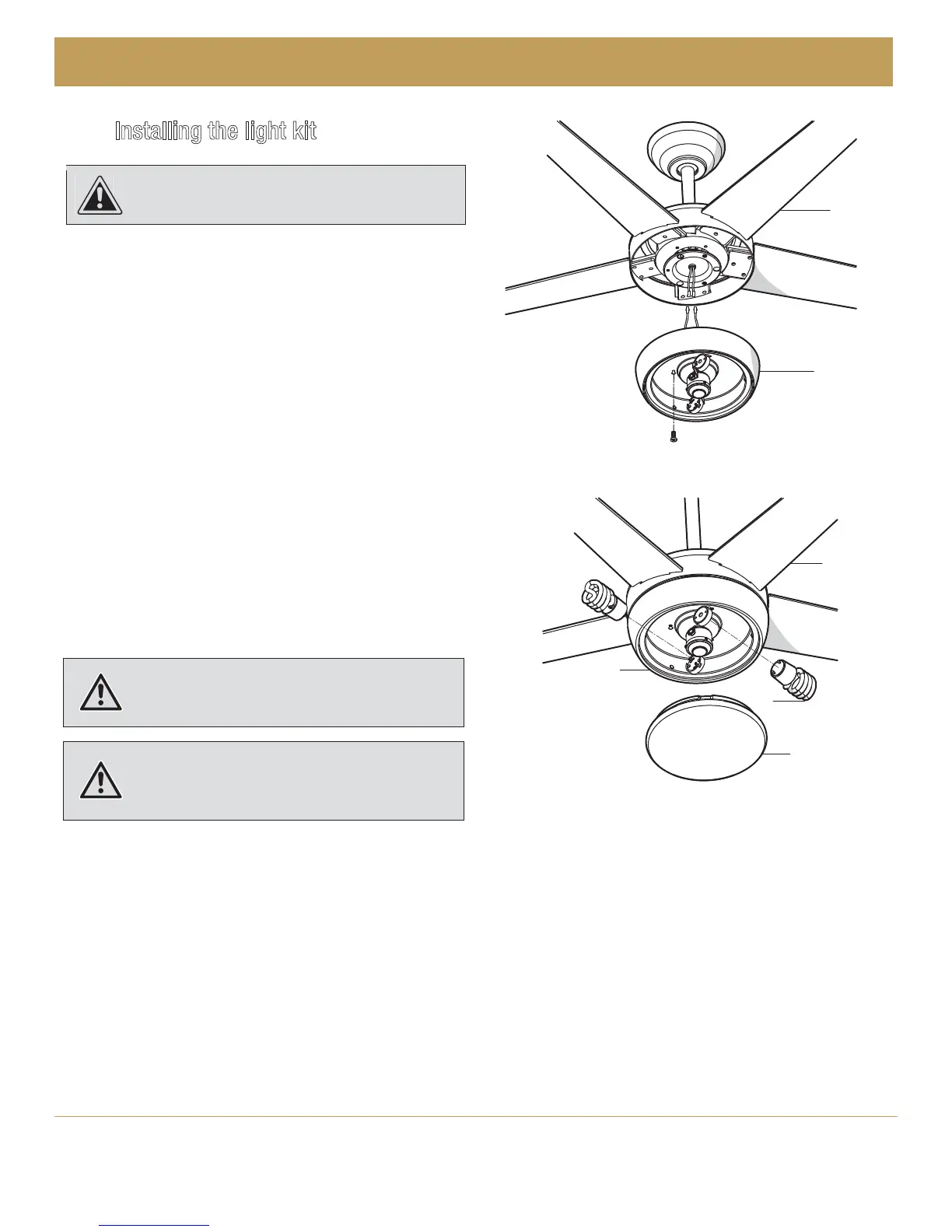
Installing the light kit
Ƒ
Ƒ Connect the blue wire exiting the bottom of the fan motor
assembly with the black wire from the top of the light kit
tter assembly (E).
Connect the white wire exiting the bottom of the fan motor
assembly with the white wire from the top of the light kit
tter assembly (E).
Ƒ Remove one screw from the black bracket below the fan
motor assembly. Loosen, but do not remove the other two
screws.
Ƒ Attach the light kit assembly (E) to the fan motor assembly
by securing with the two screws loosened in rst step.
Push the light kit assembly (E) up to engage the screw heads in
the screw slots and turn to secure. Tighten each screw rmly.
Ƒ With the power off, install the two uorescent bulbs (J)
(Max. 13W, provided) into the light bulb sockets.
Ƒ Place the glass shade (I) into the light kit assembly,
aligning the three at areas on the top ange of the glass
shade (I) with the three raised dimples in the light kit
assembly. Turn the glass shade (I) clockwise until it stops.
CAUTION:
To reduce the risk of electrical shock,
disconnect the electrical supply circuit to the fan before
installing the light kit.
WARNING: Do not overtighten when installing the glass
shade into the light kit assembly. When replacing the bulbs,
allow the glass shade to cool completely before removing.
CAUTION: Over lamping the fan will result in the fan lights
shutting down until the proper wattage of bulbs are installed.
Reset the lights by turning off the light and replacing the
bulbs with the correct wattage bulbs.
G
E
I
J
E
G