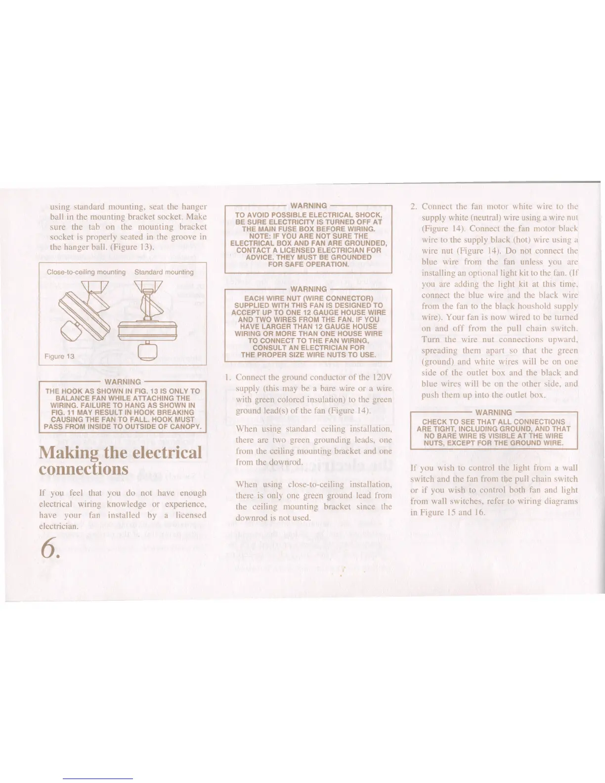
using standard mounting, seat the hanger
ball in the mounting bracket socket. Make
sure the tab on the mounting bracket
socket is properly seated in the groove in
the hanger ball. (Figure 13).
Close-to-ceilinq mounting Standard mounting
Figure 13
..------ WARNING --------.
THE HOOK AS SHOWN IN FIG. 131S ONLY TO
BALANCE FAN WHILE ATTACHING THE
WIRING. FAILURE TO HANG AS SHOWN IN
FIG. 11 MAY RESULT IN HOOK BREAKING
CAUSING THE FAN TO FALL. HOOK MUST
PASS FROM INSIDE TO OUTSIDE OF CANOPY.
Making the electrical
connections
If you feel that you do not have enough
electrical wiring knowledge or experience.
have your fan installed by a licensed
electrician.
6.
,------- WARNING -------,
TO AVOID POSSIBLE ELECTRICAL SHOCK,
BE SURE ELECTRICITY IS TURNED OFF AT
THE MAIN FUSE BOX BEFORE WIRING.
NOTE: IF YOU ARE NOT SURE THE
ELECTRICAL BOX AND FAN ARE GROUNDED,
CONTACT A LICENSED ELECTRICIAN FOR
ADVICE. THEY MUST BE GROUNDED
FOR SAFE OPERATION.
,------- WARNING -----..,
EACH WIRE NUT (WIRE CONNECTOR)
SUPPLIED WITH THIS FAN IS DESIGNED TO
ACCEPT UP TO ONE 12 GAUGE HOUSE WIRE
AND TWO WIRES FROM THE FAN. IF YOU
HAVE LARGER THAN 12 GAUGE HOUSE
WIRING OR MORE THAN ONE HOUSE WIRE
TO CONNECT TO THE FAN WIRING,
CONSULT AN ELECTRICIAN FOR
THE PROPER SIZE WIRE NUTS TO USE.
I. Connect the ground conductor of the 120Y
supply (this may be a bare wire or a wire
with green colored insulation) to the green
ground lead(s) of the fan (Figure 14).
When using standard ceiling installation.
there are two green grounding leads. one
from the ceiling mounting bracket and one
from the downrod.
When using close-to-ceiling installation.
there is only one green ground lead from
the ceiling mounting bracket since the
downrod is not used.
2. Connect the fan motor white wire to the
supply white (neutral) wire using a wire nut
(Figure 14). Connect the fan motor black
wire to the supply black (hot) wire using a
wire nut (Figure 14). Do not connect the
blue wire from the fan unless you are
installing an optional light kit to the fan. (If
you are adding the light kit at this time.
connect the blue wire and the black wire
from the fan to the black houshold supply
wire). Your fan is now wired to be turned
on and off from the pull chain switch.
Turn the wire nut connections upward.
spreading them apart so that the green
(ground) and white wires will be on one
side of the outlet box and the black and
blue wires will be on the other side, and
push them up into the outlet box.
.-------- WARNING --------.
CHECK TO SEE THAT ALL CONNECTIONS
ARE TIGHT, INCLUDING GROUND, AND THAT
NO BARE WIRE IS VISIBLE AT THE WIRE
NUTS, EXCEPT FOR THE GROUND WIRE.
If you wish to control the light from a wall
switch and the fan from the pull chain switch
or if you wish to control both fan and light
from wall switches. refer to wiring diagrams
in Figure 15 and 16.
 Loading...