Finishing the fan
installation
STANDARD CElLI 'G. IOUNTING
~----- WARNING--------.
WHEN USING THE STANDARD BALUDOWNROD
MOUNTING, THE TAB IN THE RING AT THE
BOTIOM OF THE MOUNTING BRACKET MUST
REST IN THE GROOVE OF THE HANGER BALL
FAILURE TO PROPERLY SEAT THE TAB IN THE
GROOVE COULD CAUSE DAMAGE TO WIRING.
I. Align the locking slot. of the ceiling
canopy with the two screw s in the
mounting bracket. Push up to engage the
slots and turn clockwise to lock
111
place
Immediately tighten the two moun ng
screws firmly.
2. Install the remaining two mounting screws
into the holes in the canopy and tighten
firmly.
3. Install the decorative canopy ring by
aligning the ring's slots with the screws in
the canopy. Rotate the ring clockwise to
lock in place.
4. You may now proceed to attaching the fan
blades.
8.
CLOSF- TO-CEil
I G 1
t
TI
G
I. Car
-fully
unhook the fan from the
mounung bracket and align the locking
lots of the ceiling canopy with the two
crews in the m mung bracket, Push lip to
engage the lots a d turn clockwi e to loc
r
I
ce I nmedat
'I
tighten the tv
0
uounting screw ~ firmly.
...------WARNING--------.
LOCKING SLOTS OF CEILING CANOPY ARE
PROVIDED ONLY AS AN AID TO MOUNTING.
DO NOT LEAV FAN ASSEMBLY
UNATIENDED U TIL ALL FOUR CANOPY
SCREWS ARE ENGAGED AND F RML Y
TIGHTENED.
2. Install the remaining two mounting screws
into the holes
III
the
C-.Jl0P)
and tighten
firmly.
3. Install the decorative canopy ring by
aligning the ring's slots with the screws in
the canopy. Rotate the ring clockwise to
lock in place.
4. You may now proceed to attaching the fan
blades.
.------- CAUTION------,
DO NOT OPERATE FAN UNTIL BLADES ARE IN
PLACE. NOISE AND FAN DAMAGE COULD
RESULT.
Attaching the fan
blades
Your
f n features revel on irv advancement
foi qui ex and easy blade n all, t on
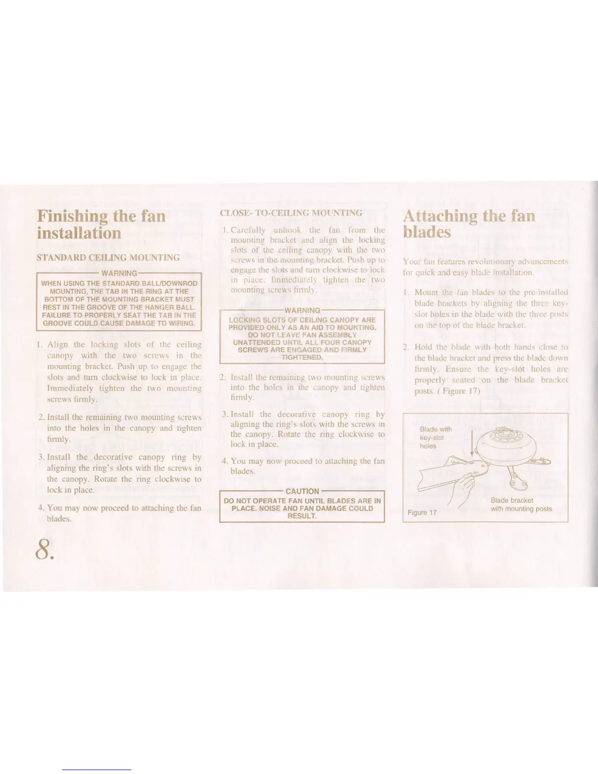
MOl nt the fan lad s to the
pre-in
talld
blade brackets bv alignmc the th-e key
slot holes in he blade \V ith the th po t
on the"ton of the blade bruck t
2 Hold the blade with both hanc (lose t<
the blade bracket and press the blade down
firmly.
r
nsure the key-slot holes a e
properly seated on the blade bracket
posts ( Figure 17)
Figure 17
Blade with
key-slot
holes