11
HAMPTONBAY.COM
Please contact 1-877-527-0313 for further assistance.
Assembly - Attaching the accessories
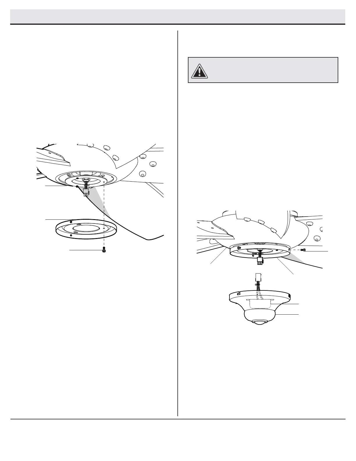
Attaching the switch cup
Attaching the switch cup adaptor
2
1
□ Remove one screw (UU) from the switch cup adaptor (H).
Loosen but do not remove the other two screws (UU).
□ Connect the molded adaptor plug of the receiver (NN) in the
switch cup (E) with the molded adaptor of the fan motor
assembly (D).
□ Aligning the “L” shape holes on the switch cup (E) with the
screws on the switch cup adaptor (H). Turn the switch cup
(E) to hold it in position.
□ Install the other screw (UU) that was removed in the rst
step. Tighten all 3 screws (UU) securely.
□ Remove one screw (QQ) from the black bracket below the
fan motor assembly (D). Loosen, but do not remove the
other two screws.
□ Align the key hole slots in the switch cup adaptor (H) with
the two screws in the black bracket.
□ Turn the switch cup adaptor (H) clockwise until the two
screws are situated in the narrow end of the keyholes.
□ Re-install the one screw (QQ) that was removed in rst
step. Tighten all three screws rmly.
H
QQ
D
E
NN
UU
H
D
CAUTION: To reduce the risk of electric shock, disconnect
the electrical supply circuit to the fan before installing the
switch cup.
 Loading...