5
STEP 4:
ATTACHE TRACK TO CEILING
1. Raise the track assembly to the ceiling. Mark the mounting holes locations with a pencil. Insure the
floating live-end connector body is positioned over the ceiling outlet box.
2. Drill hole suitable for the fasteners you will be using. Toggle bolts supplied with the track requires 5/8
inches hole.
3. Insert the toggle bolts through the holes near the ends of the track. Screw bolts into the toggle wings
two or three turns.
4. Push toggle bolts into the holes drilled into the ceiling and tighten toggle bolts until the track is about
1/4 inch from the ceiling. Do not fully tighten toggle bolts until after electrical connections are made.
STEP 5:
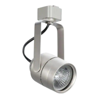
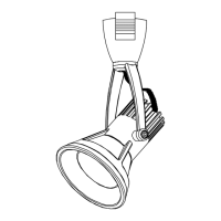
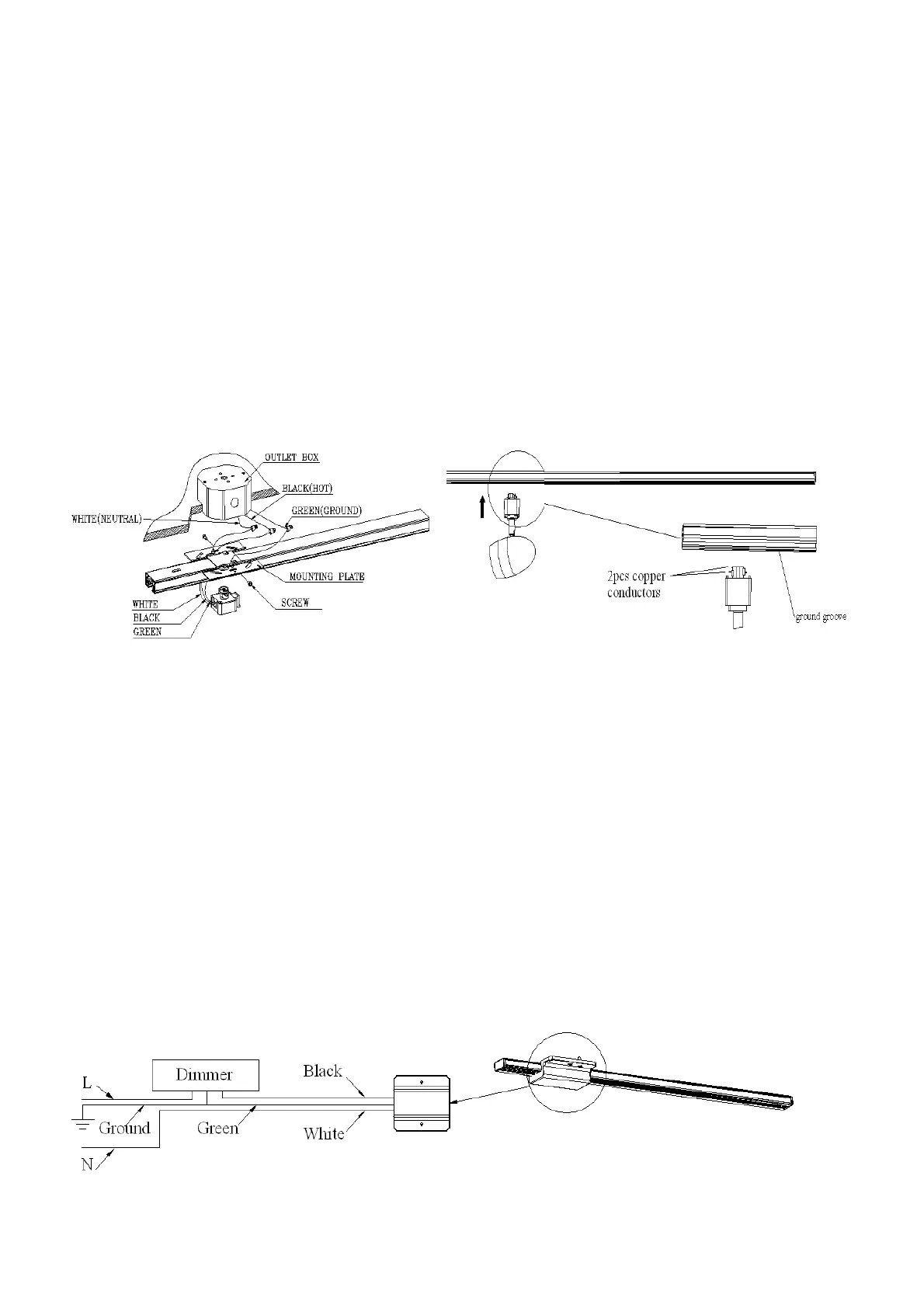
INSTALL AND REMOVAL OF TRACK HEAD (REFER TO Fig. 5)
Fig. 4 Fig. 5
INSTALLATION
1. Push the top portion of the single track luminaire adaptor into the slot of the track section.
2. Pull down the adaptor’s locking tab.
3. Turn the 2 pcs copper conductors 90 degrees towards the ground groove on the track section.
REMOVAL
1. Pull down the adaptor’s locking tab.
2. At the same time, rotate the adaptor 90 degrees and remove from track.
NOTE: ASSEMBLY THE TRIAC DIMMER (REFER TO Fig. 6)
Fig. 6
 Loading...