6
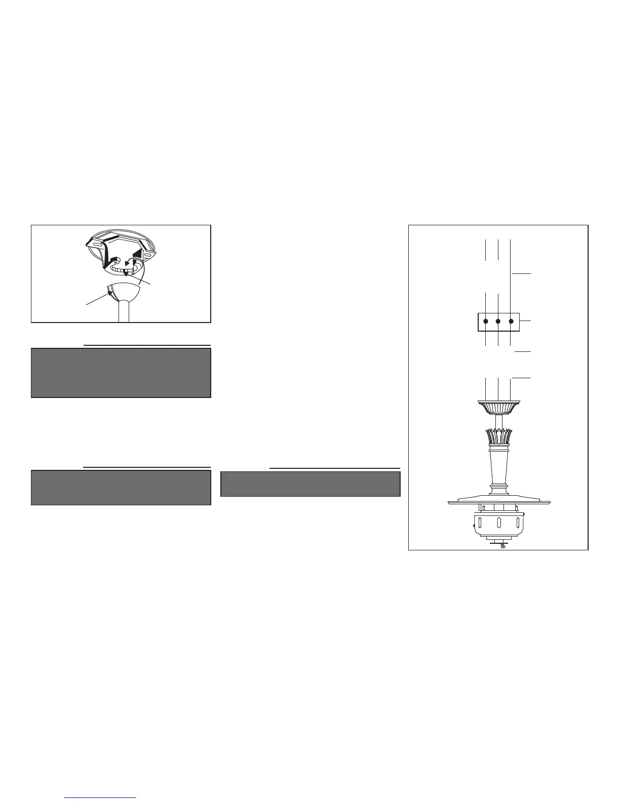
Figure 8
Groove
Tab
WARNING
THE TAB IN THE RING MUST REST IN THE
GROOVE OF THE HANGER BALL AS FIGURE 8.
FAILURE TO PROPERLY SEAT THE TAB IN
THE GROOVE COULD CAUSE DAMAGE TO
WIRING.
Making the Electrical
Connections
WARNING
TO AVOID POSSIBLE ELECTRICAL SHOCK, BE
SURE ELECTRICITY IS TURNED OFF AT THE
MAIN FUSE BOX BEFORE WIRING.
If you feel you do not have enough electrical
wiring knowledge or experience, have your fan
installed by a licensed electrician.
Follow the steps below to connect the fan to your
household wiring. Use the wire nuts supplied with
your fan. Secure the wire nuts with electrical tape.
Make sure there are no loose strands or
connections.
Connect the fan supply (black) wire to the
black household supply wire as shown in
Figure 9.
Connect the neutral fan (white) wire to the
white neutral household wire.
Connect the fan ground wire (green) to the
household ground wire.
After connecting the wires, spread them apart
so that the green and white wires are on one
side of the outlet box and the black wires are on
the other side.
Turn the wire nut connections upward and
push the wiring into the outlet box.
1.
2.
3.
4.
5.
SUPPLY CIRCUIT
Figure 9
Ground
Conductor
Outlet Box
Green Ground
Lead
GREEN
Ground to
Downrod
BLACKBLACK
WHITEWHITE
CAUTION
DO NOT USE WITH WALL LIGHT DIMMER
SWITCH.