Do you have a question about the HAMPTON BAY Bercello Estates II and is the answer not in the manual?
Do not use solid-state fan speed controls to prevent permanent damage to the fan's electronic circuitry.
Do not bend blade holders during installation, balancing, or cleaning; avoid inserting foreign objects between blades.
Mount fan only to UL-listed outlet boxes marked for fan support, using provided screws.
The fan has a 190W limiter; exceeding this may prevent the light kit from working.
Do not install or use the fan if any part is damaged or missing. Contact support.
Details on how to mount the fan, including requirements for outlet boxes and support structures.
Mount fan only to UL-listed outlet boxes marked for fan support using provided screws.
Proper installation of the cotter pin is critical to prevent the fan from loosening and falling.
Mount fan only to an outlet box or supporting system marked acceptable for fan support and use provided mounting screws.
Ensure the tab in the ring rests in the hanger ball groove to prevent wiring damage.
Ensure electricity is turned off at the main fuse box before performing any wiring.
The fan must be installed within 40 feet of the transmitter for optimal signal transmission.
Do not use the fan with a wall light dimmer switch, as it may cause malfunction.
Ensure all connections, including ground, are tight and no bare wire is visible except for the ground wire.
Ensure the tab on the hanger bracket sits in the hanger ball groove before attaching the canopy.
Electrical diagrams are for reference; use only UL-listed light kits suitable for this fan.
Do not bend blade holders during installation, balancing, or cleaning; avoid inserting objects between blades.
Procedure to correct fan wobble by checking blade levels and using the balancing kit.
Always disconnect power at the circuit breaker or fuse box before starting installation to prevent electric shock.
Always disconnect power at the circuit breaker or fuse box before starting installation to prevent electric shock.
Exceeding the 190W limit for the light kit may prevent it from functioning.
Install 12V MN21/A23 battery; remove if not used for long periods to prevent damage.
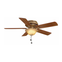
Use HI, MED, LOW buttons to set fan speed; OFF button turns the fan off.
Use the light button to turn the light ON/OFF or press and hold to set desired brightness.
Slide switch to Left for warm weather (downward airflow), Right for cool weather (upward airflow).
Downward airflow creates a cooling effect, allowing higher AC settings.
Upward airflow moves warm air off the ceiling, allowing lower heating settings.
Check support connections, brackets, and blade attachments twice a year for security.
Use a soft brush or lint-free cloth for cleaning; avoid water to prevent damage.
Check fuses, wiring connections, and transmitter/receiver frequency settings.
Ensure motor housing screws are snug, check blade holder screws, and allow break-in period.
Check wattage limit (190W); relamp with bulbs under limit and reset power.
Details fan size, speed, voltage, amps, watts, RPM, CFM, and weight.
Motor warranted for lifetime; other parts for one year. Proof of purchase required.
Excludes damage from accident, misuse, improper installation, or accessory affixing.
Present original receipt; costs of removal/reinstallation are customer's responsibility.
| Brand | HAMPTON BAY |
|---|---|
| Model | Bercello Estates II |
| Category | Fan |
| Language | English |