12
Hampton H300 Cast Freestanding Woodstove
INSTALLATION
Horizontal Installation
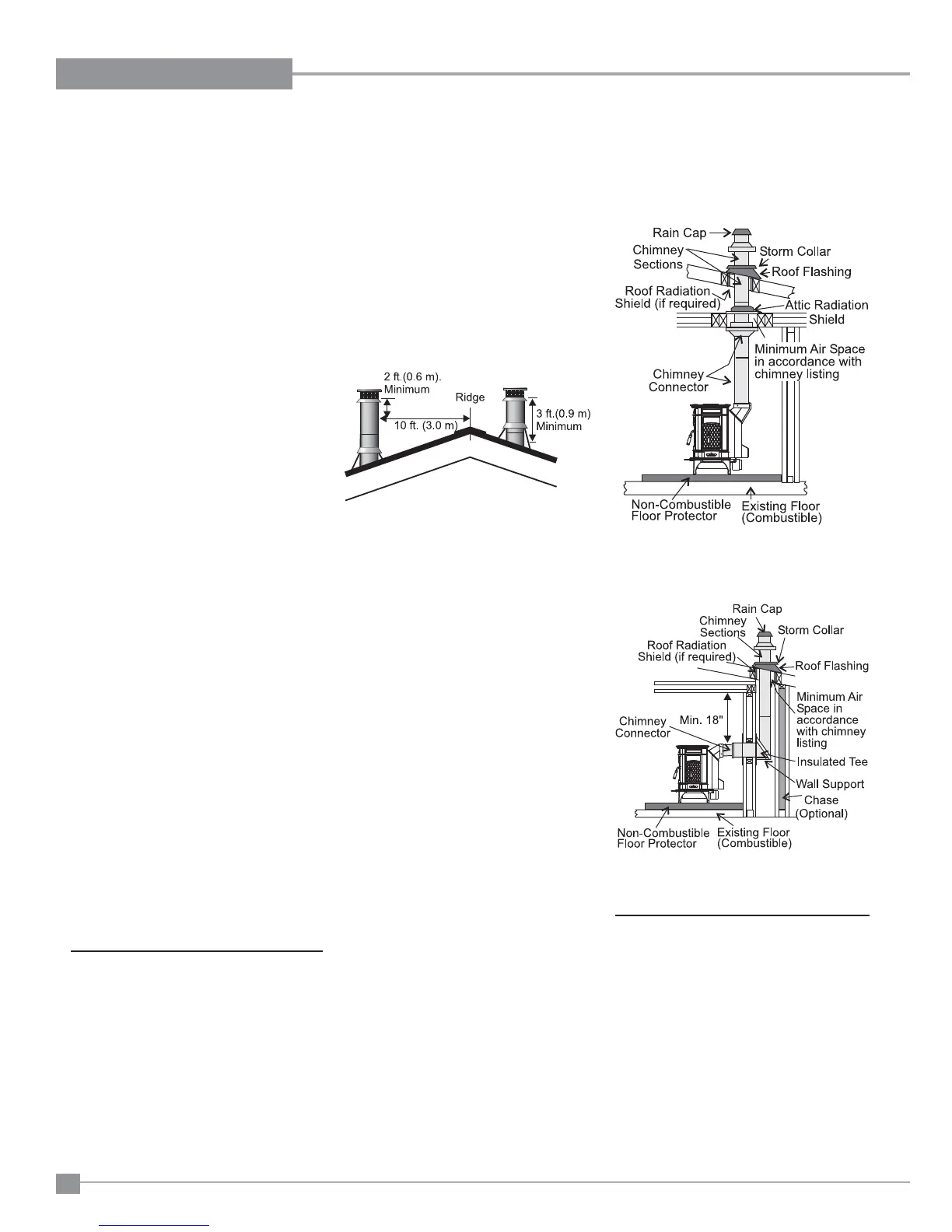
Standard Ceiling Installation
Note: Increasing the chimney height above
this minimum level will sometimes
help your unit to “breathe” better
by allowing a greater draft to be cre-
ated. This greater draft can decrease
problems such as, diffi cult start-ups,
back-smoking when door is open,
and dirty glass. It might be suffi cient
to initially try with the minimum re-
quired height, and then if problems
do arise add additional height at a
later date.
4) Slide the roof fl ashing over your chimney
and seal the fl ashing to the roof with roofi ng
compound. Secure the fl ashing to your roof
with nails or screws.
5) Place the storm collar over the fl ashing,
sealing the joints with a silicone caulking.
6) Fasten the raincap with spark screens (if
required) to the top of your chimney.
HOW TO DETERMINE IF
ALTERNATE
FLOOR PROTECTION
MATERIALS ARE
ACCEPTABLE
The specifi ed fl oor protector should be 3/8"
(18mm) thick material with a K - factor of
0.84.
The proposed alternative is 4" (100mm) brick
with a C-factor of 1.25 over 1/8" (3mm) mineral
board with a K-factor of 0.29.
Step (a):
Use formula above to convert specifi cation
to R-value.
R = 1/k x T = 1/0.84 x .75 = 0.893.
Step (b):
Calculate R of proposed system.
4" brick of C = 1.25, therefore
Rbrick = 1/C = 1/1.25 = 0.80
1/8" mineral board of k = 0.29, therefore
Rmin.bd. = 1/0.29 x 0.125 = 0.431
Total R = Rbrick + Rmineral board =
0.8 + 0.431 = 1.231.
Step (c):
Compare proposed system R of 1.231 to
specifi ed R of 0.893. Since proposed system
R is greater than required, the system is
acceptable.
DEFINITIONS
Thermal Conductance:
C = Btu = W
(hr)(ft
2
)(
o
F) (m
2)
)(K)
Thermal Conductivity:
k = (Btu)(inch) = W = Btu
(hr)(ft
3
)(
o
F) (m)(K) (hr)(ft)(
o
F)
Thermal Resistance:
R = (ft
2
)(hr)(
o
F) = (m
2
)(K)
Btu W
FACTORY
BUILT CHIMNEY
When a metal prefabricated chimney is used, the
manufacturer's installation instructions must be
followed. You must also purchase and install the
ceiling support package or wall pass-through and
"T" section package, fi restops (where needed),
insulation shield, roof fl ashing, chimney cap,
etc. Maintain proper clearance to the structure
as recommended by the manufacturer. The
chimney must be the required height above the
roof or other obstructions for safety and proper
draft operation.
7) For optimum effi ciency when installing into
a masonry chimney, size accordingly, i.e.
the 6" (152mm) fl ue dia. is 28.28 sq.in.
8) To complete your chimney installation, install
the double wall connector pipe from the
stove’s fl ue collar to the chimney support
device.
9) If you are using a horizontal connector,
the chimney connector should be as high
as possible while still maintaining the 18"
(457mm) minimum distance from the hori-
zontal connector to the ceiling.
10) NOTE: Residential Close Clearance and
Alcove installations require a listed dou-
ble wall connector from the stove collar
to the ceiling level.
The diagrams below illustrate one way to in-
stall your unit into a standard ceiling or with a
horizontal connector. Check with your dealer
or installer for information on other options
available to you.
STEP-BY-STEP
CHIMNEY AND
CONNECTOR
INSTALLATION
Note: These are a generic set of chimney
installation instructions. Always fol-
low the manufacturers own instruc-
tions explicitly. Check the Minimum
Recommended Flue Heights (Table
1).
1) With your location already established, cut
and frame the roof hole. It is recommended
that no ceiling support member be cut for
chimney and support box installation. If it is
necessary to cut them, the members must
be made structurally sound.
2) Install radiant shield and support from
above.
3) Stack the insulated pipe onto your fi nish
support to a minimum height of 3 feet above
the roof penetration, or 2 feet above any
point within 10 feet measured horizontally.
There must be at least 3 feet of chimney
above the roof level.