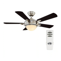
This document is a comprehensive Use and Care Guide for the Hampton Bay Mena 54-inch Ceiling Fan, providing detailed instructions for installation, operation, and maintenance. It is designed to assist users in safely and effectively setting up and using their new ceiling fan.
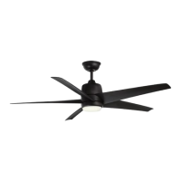
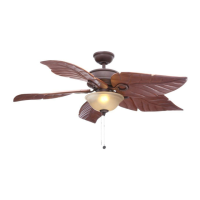
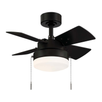
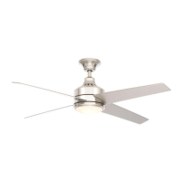
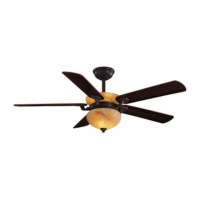
The Hampton Bay Mena 54-inch Ceiling Fan is a residential ceiling fan designed to provide air circulation and illumination. Its primary function is to create airflow for cooling in warm weather and to assist in heat distribution in cool weather, while also offering integrated lighting. The fan is equipped with a remote control for convenient operation of its various features.
Installation and Assembly:
The installation process begins with preparing the mounting bracket. Users are instructed to remove the canopy ring and the mounting bracket from the canopy, saving the canopy screws for later use. This initial step ensures that the mounting bracket is ready to be secured to the ceiling outlet box.
Next, the guide details how to route the electrical wires. The wires exiting the fan motor assembly must be carefully threaded through the center of the canopy ring and then through the ball/downrod assembly. The decorative motor collar cover is also slid onto the downrod at this stage. Proper routing of these wires is crucial for both electrical connection and aesthetic integration.
Assembling the fan involves attaching the ball/downrod assembly to the fan-motor assembly. This step requires loosening setscrews on the motor collar, aligning holes, and carefully inserting the hanger pin and then the locking pin. A critical warning emphasizes the importance of properly installing the locking pin to prevent the fan from becoming loose or falling. The setscrews are then re-tightened to ensure a secure connection.
Attaching the fan to the electrical box is a key safety step. The guide warns users to mount the fan to a UL-listed outlet box marked "Acceptable for fan support of 35 lbs. (15.9 kg) or less," using the screws provided with the outlet box. It also advises consulting a qualified electrician if there is any doubt about the outlet box's suitability. The mounting bracket is designed to slide onto the outlet box screws, and the 120-Volt supply wires are passed through the bracket's center hole. Leveling washers may be used if necessary, and the mounting screws are securely tightened.
Hanging the fan involves carefully lifting the fan-motor assembly and inserting the ball portion of the downrod into the socket of the slide-on mounting bracket. The downrod assembly is then turned clockwise until it is seated with the tab of the mounting bracket aligned with the slot in the ball. This ensures the fan is properly suspended.
The remote control setup is an important part of the installation. Users are guided to set the code on both the receiver and the remote control, ensuring they match. This involves removing the battery cover from the remote, setting the DIP switches, and installing the A23 12V battery. The receiver is then wired to the household wiring, with clear instructions on connecting green, black/red, and white wires using wire connecting nuts. Warnings are provided regarding electrical shock and the proper use of wire nuts.
Wiring the fan to the receiver involves connecting the molded adaptor plug from the receiver to the fan motor assembly's molded adaptor. If a longer downrod is desired, an extension lead wire is provided and connected in a similar manner.
Mounting the fan-motor assembly (standard mount) involves aligning the locking slots of the canopy with the mounting bracket screws, pushing up to engage the slots, and turning clockwise to lock in place. The mounting screws are then firmly tightened. Finally, the decorative canopy ring is installed by aligning its slots with the canopy screws and rotating it clockwise to lock.
Attaching the fan blades is a straightforward process. Each blade is inserted into a slot in the fan motor housing until it stops, and a locking clip clicks into place. Users are instructed to pull the fan blade away from the motor housing to ensure it is securely snapped into the locking clip. The process is repeated for all remaining blades. Removing the blades involves squeezing the tabs of the locking clip and pulling the blade away from the motor housing.
Attaching the light kit fitter assembly involves connecting the wires from the light kit to the fan motor assembly using molded adaptor plugs. All wires and splices are carefully tucked into the switch cup, and the safety cable from the light kit is connected to the hook from the motor assembly. The light kit assembly is then pushed up to the motor assembly, aligning the magnet part until it is secure.
Operation:
The fan is operated using a remote control, which allows users to adjust fan speed and control the lights. The guide explains that speed settings depend on factors like room size and ceiling height.
The fan includes a reversing switch (YY) located on the top of the motor housing. In warm weather, the fan is typically set to circulate air downward (forward mode) to create a cooling effect. In cool weather, the reversing switch can be slid to the opposite position to move warm air off the ceiling (reverse mode), assisting with heat distribution. Users are advised to turn off the fan and wait for the blades to stop before changing the reversing switch position.
The remote control features a power ON/OFF button for the fan and light. Fan speed is controlled by a dedicated button, with LEDs indicating the selected speed (high, medium, low). The light ON/OFF button controls the illumination, and pressing and holding it activates the dimmer function.
A unique feature is the Correlated Color Temperature (CCT) changing function. The default light temperature is 3000K (Soft White). Users can cycle through three color temperature options (2700K Warm White, 3000K Soft White, and 5000K Daylight) by pushing and releasing the CCT button.
Maintenance:
The guide emphasizes the importance of regular maintenance to ensure the fan's longevity and optimal performance. A crucial safety warning advises users to turn off the power before cleaning the fan.
Due to the fan's natural movement, some connections may loosen over time. Users are instructed to check the support connections, brackets, and blade attachments twice a year to ensure they are secure. It is not necessary to remove the fan from the ceiling for these checks.
Periodic cleaning is recommended to maintain the fan's appearance. The guide explicitly warns against using water for cleaning, as it can damage the motor, wood, or cause electrical shock. Instead, a soft brush or lint-free cloth should be used to avoid scratching the finish. For added protection and beauty, a light coat of furniture polish can be applied to the wood, and small scratches can be covered with shoe polish.
The fan motor is permanently-lubricated and sealed, meaning it does not require oiling.
Troubleshooting tips are provided for common issues. If the fan does not start, users should check circuit fuses or breakers, wire connections, remote control battery, and ensure they are within the normal operating range. For noisy fans, checking motor housing screws, blade bracket screws, wire nut connections, and allowing a 24-hour "breaking in" period are suggested. If a light kit is installed, screws securing glassware and light bulbs should be checked. For wobbling fans, ensuring all blade and blade arm screws are secure and checking blade levels are recommended. A balancing kit can be requested if wobbling persists after these checks.