Do you have a question about the HAMPTON BAY SW20006 ORB and is the answer not in the manual?
Guidelines for safe electrical connections, wiring, and mounting.
Steps for mounting the bracket and attaching the downrod to the motor.
Procedure for making safe and secure electrical wire connections.
How to attach fan blades and install the mounting plate.
Attaching the light kit plate and installing LED bulbs.
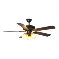
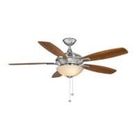
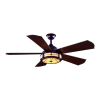
This document outlines the installation, operation, and maintenance of the Hampton Bay Claret LED 52-inch Ceiling Fan. This ceiling fan is designed to provide both air circulation and illumination for your home, offering a blend of functionality and style. The fan is available in several finishes, including Oil Rubbed Bronze (ORB), Matte Black (MBK), and Brushed Nickel (BN), allowing it to complement various interior designs.
The primary function of this device is to circulate air within a room, helping to regulate temperature and improve comfort. It features a 52-inch blade span, making it suitable for medium to large rooms. In addition to air circulation, the fan incorporates an LED light kit, providing ambient lighting. The fan's operation is controlled via pull chains, offering a straightforward and accessible method for adjusting fan speed and light settings.
Installation of the Hampton Bay Claret LED 52-inch Ceiling Fan requires careful attention to electrical safety and proper mounting procedures. Before beginning any installation steps, it is crucial to ensure that the electricity to the circuit breaker or fuse box is turned off to prevent electric shock. All wiring must comply with the National Electrical Code "ANSI/NFPA 70-1999" and local electrical codes, and installation should ideally be performed by a qualified, licensed electrician. The outlet box and its support structure must be securely mounted and capable of reliably supporting a minimum of 35 lbs, and only UL Listed outlet boxes marked "FOR FAN SUPPORT" should be used. Plastic outlet boxes are not recommended for fan support.
The fan must be mounted with a minimum of 7 ft. clearance from the trailing edge of the blades to the floor to ensure safety and optimal performance. During installation, it is important to avoid bending the blade arms (flanges) to prevent personal injury or damage to the fan. Foreign objects should never be inserted between the rotating fan blades. When making electrical connections, spliced conductors should be turned upward and carefully pushed into the outlet box, with wires spread apart to ensure proper grounding and prevent short circuits. All setscrews should be checked and retightened where necessary before and after installation to ensure stability.
The installation process begins with attaching the mounting bracket to the electrical box. The slots on the mounting bracket are placed over the two mounting screws provided with the outlet box, then slid into place at the narrow section of the slots and securely tightened. Next, the downrod is attached to the fan motor assembly. This involves removing the hitch pin and lock pin from the downrod, then removing the hanger ball by loosening its set screw and removing the cross pin. The fan wires are carefully fed up through the downrod, which is then threaded into the fan motor assembly coupling. The holes are aligned, the lock pin and hitch pin are replaced, and the set screws are tightened.
Following this, the coupling cover, canopy cover, and canopy are slipped onto the downrod. The hanger ball is then reinstalled onto the downrod, ensuring the cross pin is in the correct position, the set screws are tight, and the wires are not twisted. The fan motor assembly is then lifted into position, and the hanger ball is placed into the mounting bracket. The fan motor assembly is rotated until the check groove drops into the registration slot and seats firmly, preventing the downrod from rotating.
Electrical connections are a critical step. The fan supply (black) wire and light supply (blue) wire are connected to the black household supply wire. The neutral fan (white) wire is connected to the white neutral household wire. The ground wire (green or bare copper) from the outlet box is connected to the ground wire of the hanging ball and the ground wire of the mounting bracket. These connections are secured with wire nuts and wrapped with electrical tape. After connecting, the wires are spread apart, with green and white wires on one side of the outlet box and black and blue wires on the other, then carefully tucked into the outlet box.
The canopy and canopy cover are then installed. One screw is removed from the mounting bracket, and another is loosened. The canopy is raised to the mounting bracket, ensuring the loosened screw is inserted into the keyhole in the canopy. The canopy is rotated clockwise until it locks, then secured by replacing and tightening the screws. The canopy cover is placed on the canopy and rotated clockwise until it locks into position.
Attaching the fan blades involves inserting each blade through the slot on the fan motor assembly and securing it with three blade screws and three fiber washers. This process is repeated for all five blades. Next, the mounting plate is installed to the fan motor assembly. One screw is removed from the locking plate of the fan motor assembly, and two others are loosened. The keyholes from the mounting plate are placed over the loosened screws, and the plate is turned until it locks at the narrow section of the keyholes. It is then secured by tightening the loosened screws and replacing the removed screw.
The light kit installation involves attaching the light kit plate to the mounting plate. One screw is removed from the mounting plate, and two others are loosened. While holding the light kit plate under the fan, the wire connection plugs are firmly snapped together. The keyholes from the light kit plate are placed over the loosened screws, and the plate is turned until it locks. It is then secured by tightening the loosened screws and replacing the removed screw. Finally, the two 9W LED bulbs are installed into the sockets, and the glass is attached to the light kit plate by twisting it tightly, taking care not to overtighten. The pull chain fob is then attached to the chain on the light kit plate.
Once installed, the fan's operation is controlled by two pull chains. The 3-speed pull chain controls the fan speed: one pull for High, two for Medium, three for Low, and four for Off. The light kit pull chain turns the light kit "ON" or "OFF." The fan also features a reverse function, controlled by a reverse switch located on the surface of the light kit plate. This switch allows the fan to operate in either forward (switch left) or reverse (switch right) direction. For warm weather, a counterclockwise direction creates a downward airflow, providing a cooling effect. For cool weather, a clockwise direction moves warm air off the ceiling, helping to distribute heat. It is important to wait for the fan to stop before reversing the direction of the blade rotation.
Maintenance of the Hampton Bay Claret LED 52-inch Ceiling Fan is relatively simple. It is recommended to check the support connections, brackets, and blade attachments twice a year to ensure they are secure. Due to the fan's natural movement, some connections may loosen over time, but it is not necessary to remove the fan from the ceiling for these checks. Cleaning the fan periodically with a soft brush or lint-free cloth is advised to avoid scratching the finish. The plating is sealed with a lacquer to minimize discoloration or tarnishing. Water or detergents should not be used for cleaning, as they can damage the motor, wood, or cause an electrical shock. A dry dust cloth or lightly dampened cloth is suitable for most cleaning. Applying a light coat of furniture polish to the wood blades or covering small scratches with a light application of shoe polish are optional maintenance steps. It is important not to apply oil to the fan or motor, as the motor has permanently-lubricated sealed ball bearings.
Troubleshooting common issues is also covered. If the fan does not start, check the main and branch circuit fuses or breakers, and verify line wire connections to the fan and switch wire connections in the switch housing. Also, ensure the dip switches from the remote control and receiver are set to the same frequency. If the fan sounds noisy, check that all motor housing screws are snug, and that the screws attaching the fan blade arm to the motor hub are tight. Ensure wire nut connections are not rattling against each other or the interior wall of the switch housing. A 24-hour "breaking-in" period is often needed, as most noises associated with a new fan disappear during this time. If using the ceiling light kit, confirm that the screws securing the glassware are tight and that the light bulb is secure.
For fan wobble issues, ensure there is a short distance from the ceiling to the canopy and that it does not touch the ceiling. Verify that the ceiling box is secure and that rubber isolator pads are used between the mounting bracket and outlet box. Check that all blade and blade arm screws are secure. Most fan wobble problems are caused by unequal blade levels. To check this, select a point on the ceiling above the tip of one blade and measure from the center of each blade to that point on the ceiling. Rotate the fan and repeat for each blade. Measurements should deviate by no more than 1/8 inch. Run the fan for 10 minutes after checking. If wobble is still noticeable, use the enclosed blade balancing kit, which includes additional instructions. Always ensure the power is off at the electrical panel box before attempting any repairs.
| Brand | HAMPTON BAY |
|---|---|
| Model | SW20006 ORB |
| Category | Fan |
| Language | English |