5.
Figure 7
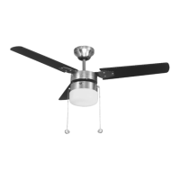
Figure 8
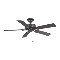
Figure 9
Downrod Cover
Pin in
Locked
Position
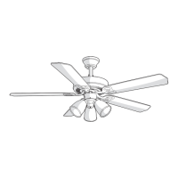
Locking Pin
Hanger Pin
Motor Collar Cover
Canopy Ring
Canopy
Downrod/Ball
Assembly
Motor Wires
Hook
Ceiling
Mounting
Plate
Mounting
Screws
(Supplied With
Outlet Box)
UL Listed
Outlet Box
Slide Mounting
Plate Over
Screw Heads
120V Wires
Reversing
Switch
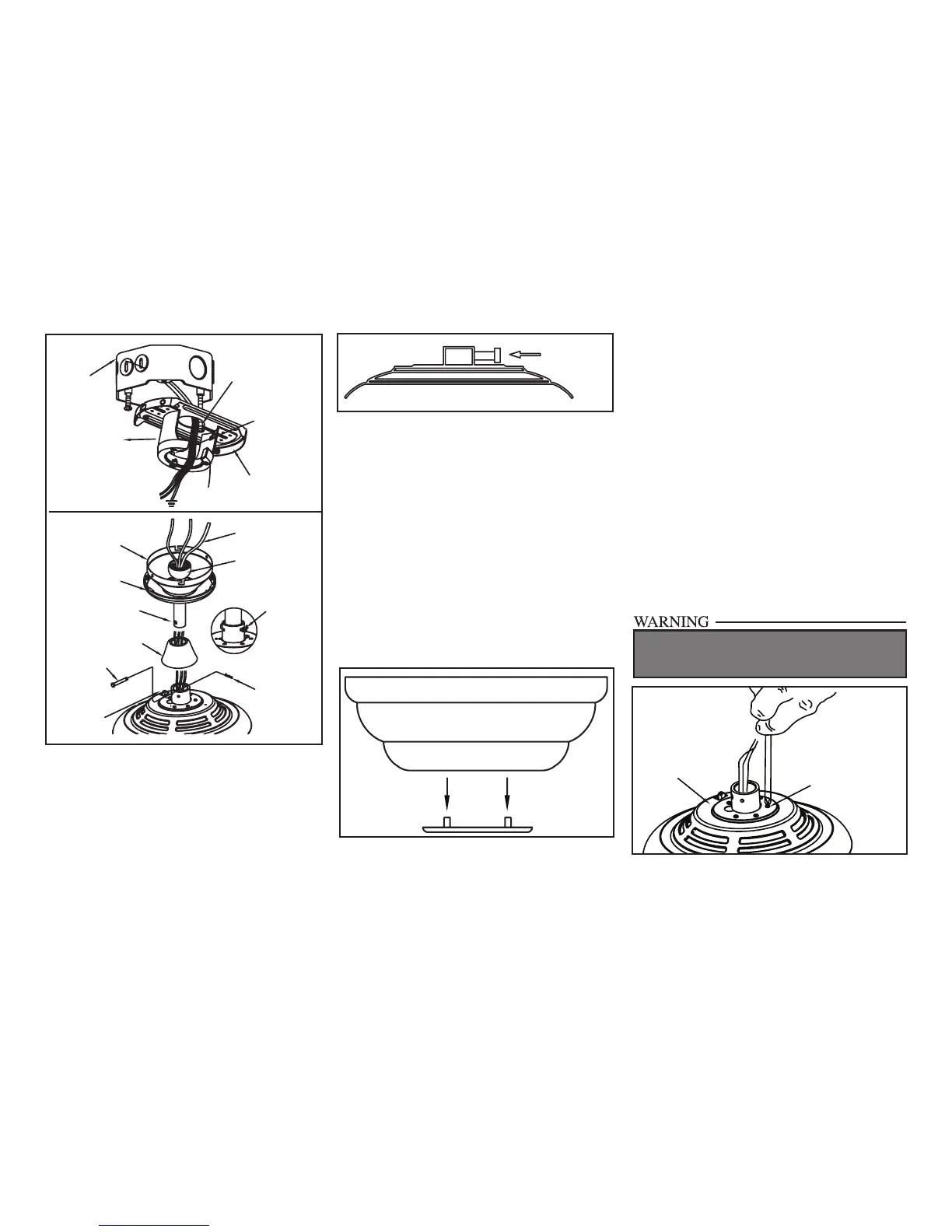
FAILURE TO COMPLETELY TIGHTEN THE
THREE SCREWS IN STEP 7 COULD RESULT IN
FAN LOOSENING AND POSSIBLY FALLING.
Tighten Set
Screw
“Close-to-Ceiling” Mounting
1. Remove canopy ring from the canopy by
turning the ring to the right until it unlocks
(Figure 5).
2. Remove the mounting plate from the canopy
by loosening the four screws on the top of the
canopy. Remove the two non-slotted screws
and loosen the slotted screws. This will enable
you to remove the mounting plate (Figure 6).
3. Remove the decorative canopy bottom cov-
er from the canopy by depressing the three
studs (Figure 9).
Canopy
Bottom
Cover
4. Remove three of the six screws and lock
washers (every other one) securing the mo-
tor collar to the top of the fan motor housing
(Figure 10).
5. Place the rubber gasket over the
remaining three screws, route the wires
exiting the top of the fan motor through the
canopy ring (make sure the slot openings
are on top), then proceed to place the ceiling
canopy over the collar at the top of the motor
(Figure 11).
6. Align the mounting holes with the holes
in the motor and fasten, using the three
screws and lock-washers removed in
step 4 (Figure 11).
7. Tighten the mounting screws securely.
6. Re-tighten the set screws on the collar on top
of the motor housing (Figure 8).
7. Proceed to “Installing the Fan” section.
Figure 10
Screw and
Lockwasher
(3 of 6 screws)
Motor Collar