EN
78
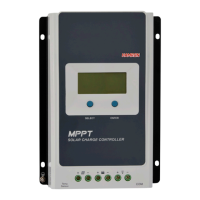
TYPE DESIGNATION STRUCTURE
Example
Tracer Joint negative terminal
1 Maximum open circuit voltage 100 V
2 System voltage 12/24 VDC
10 Charging and discharging current 10 A
AN Product series
FIG. 2
MAXIMUM POWER POINT TRACKING TECHNOLOGY – MPPT
Because of their non linear characteristics, solar panels have a distinct maximum power on their
run curve. Traditional controllers with switched charging and pulse width modulation (PWM) cannot
charge the battery at this maximum power point, and can therefore not utilise the maximum power
the solar panel can provide. Controllers with maximum power point tracking (MPPT) can nd and
follow the maximum point on the power curve and can therefore charge the battery with maximum
power. MPPT technology continuously compares and adjusts the points to nd and follow the point at
which the solar panel provides its maximum power. This takes place automatically and does not need
any settings or other action by the user. The solar panel’s run curves are shown below and it can be
seen that the solar panel has a denite maximum power point (MPP) that the MPPT technology nds
and thereby maximises the battery charging. If we assume a system eciency of 100% we get the
following equations.
Input power (P
PV
) = Power output (P
Bat
)
Input voltage (U
Mpp
) x Input current (I
PV
) =
Battery voltage (U
Bat
) x Battery current (I
Bat
)
Normally U
Mpp
is higher than U
Bat
, which because of the law on the conservation of energy means
that I
Bat
is higher than I
PV
. The greater the dierence between U
Mpp
and U
Bat
, the greater the
dierence between I
PV
and I
Bat
. The greater the dierence between the solar panel and battery, the
more the conversion eciency of the system drops. The eciency of the charge controller is therefore
very important for the solar panel system. The shadowed area in diagram 3 shows the charging range
for charge controllers with traditional PWM technology. The higher charging power available with
MPPT technology can be clearly seen. According to our measurements MPPT controllers can utilise
from 20 to 30% more of the solar power than PWM controllers. (This value can vary, depending on
the surrounding conditions and energy losses.)
1. Current (A)
2. Charging range with traditional technology
3. Voltage (V)
4. Current