EasyManua.ls Logo

Hamworthy MILBORNE381 Series User Manual

Hamworthy MILBORNE381 Series
72 pages
To Next Page IconTo Next Page
Page #1 background imageLoading...
Page #1 background image
HAMWORTHY HEATING LTD
MILBORNE
500001130/J
MILBORNE BOILERS
Wall Hung, Pre-Mix, Condensing,
Modular Boilers
381 & 501 Series
Design Installation, Commissioning
and Operating Instructions
NATURAL GAS
I
2H
LPG - PROPANE
I
3p
i
NOTE: THESE INSTRUCTIONS SHOULD BE READ AND UNDERSTOOD BEFORE
ATTEMPTING TO INSTALL, COMMISSION OR OPERATE THIS UNIT
PUBLICATION NO. 500001130
ISSUE ‘J’
JULY 2009

Table of Contents

Question and Answer IconNeed help?

Do you have a question about the Hamworthy MILBORNE381 Series and is the answer not in the manual?

Hamworthy MILBORNE381 Series Specifications

General IconGeneral
BrandHamworthy
ModelMILBORNE381 Series
CategoryBoiler
LanguageEnglish

Summary

1.0 INTRODUCTION

1.1 Installation Requirements

Installation must be by a competent person following regulations.

1.2 Fuel Compatibility

Boiler is for Natural Gas (2nd Family) and LPG - Propane (3rd Family).

1.3 Boiler Description

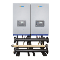
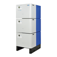
Fully modulating, pre-mix, condensing boiler, modular format up to six modules.

1.4 System Type

Suitable for unvented (pressurised) heating systems; requires safety interlocks.

3.0 SIZE AND SPACE REQUIREMENTS

4.0 SITE LOCATION AND PREPARATION

4.1 Site Location

Wall mounting and floorstanding requirements for boiler installation.

4.2 Gas Supply

Requirements for gas supply pipes, connections, testing, and purging.

4.3 Flueing

Flue System Materials and Routing

Use of polypropylene flue, compliance with regulations, and condensation drainage.

4.3 Flue Terminal Locations

4.4 Water Supply

System Requirements

Suitable for sealed (pressurised) systems; pump control recommendations.

4.5 Condensate Connections

4.6 Electrical Supply

Power Requirements and Safety

230V, 50Hz supply; earthing; isolator requirements; wiring details.

5.0 BOILER ASSEMBLY

5.2.3 Modular Boiler Installation Type C63

5.3 Water Connections

Water System Recommendations

Pipework must be self-supporting; pump management; flow rate requirements.

5.3 Electrical Connections

6.0 PRE-COMMISSIONING

6.1 Gas Supply

Ensure gas installation is tested, purged, and certificates are available.

7.0 CHECKS PRIOR TO LIGHTING

7.1 Boiler Gas System Leak Check

Procedure for performing a gas system leak check before lighting the boiler.

7.2 Checks prior to lighting the boiler

7.2.1 Pre-Lighting Checks

Checks for external controls, gas configuration (Parameter 36), system flushing, electrical connections.

7.2.2 Gas Inlet Pressure Test

Procedure to check static and dynamic gas inlet pressure.

7.3 Commissioning the Boiler

7.3.1 Flue Gas Analysis

Insert combustion analyser probe in flue for analysis.

7.4 Initial Lighting

Procedure for initial boiler lighting by competent persons.

8.0 CONTROLS OPERATION

8.1 Overview

Micro-processor based system, Master/Slave configuration, and performance monitoring.

8.2.6 Building Management System Control

8.2.7 Connection to temperature control devices

8.3 Emergency Mode

Activating Emergency Mode

Procedure to activate emergency mode by disconnecting connectors and setting switches.

8.4 Set-up for multiple boiler installations

Wiring connections

8.6 Master control panel error codes

Error Mode Display

How the display indicates faults and the procedure for identifying them.

Permanent Lock-out Reset

Procedure to reset modules in permanent lock-out using the reset button.

8.7 Users Parameter Adjustments

Adjusting Temperature Set-Points

Procedure to modify heating and DHW circuit set-points.

8.9.1 Programming Mode

Parameter Modification

Steps for scrolling, selecting, changing, and storing parameter values.

8.9.2 Combustion test parameters

Performing Combustion Test

Procedure to check combustion at max/min fan speeds and adjust gas valve.

8.10 Programming Procedure

8.10.1 Master Control Primary Functions

Setting essential parameters like sequence mode, frost protection, and gas type.

8.10.5.1 Setting heating circuit functions for 0-10v analog input (LOAD)

8.10.6.1 Setting heating circuit functions for 0-10v analog input (TEMPERATURE)

9.0 FAULT FINDING

9.1 Safety Features

Explanation of temperature limit thermostat and flame sensing safety features.

9.2 Fault Finding Procedures

Guidance on general error codes and consulting Hamworthy Heating.

9.3 Possible Causes of Boiler Lockout

Common reasons for boiler lockout, such as ignition failure or gas supply issues.

10.0 SERVICING

10.1 Regular Servicing Recommendations

Annual servicing by appointed person; 6-monthly examination; flue inspection.

10.4 Cleaning the exchanger

10.6 Cleaning the ignition electrode

APPENDIX A - GAS DATA

Natural Gas Data

General data and gas data for models 381, 382, 501, 502.

LPG Propane Data

General data and gas data for LPG conversion.

A2.2 Installation (LPG)

A2.3 Procedure for Converting boiler from Natural Gas to LPG

Step-by-step guide for converting from Natural Gas to LPG.

LPG Orifice Details

Orifice Fitting and Selection

Details on fitting 6.5mm/6.75mm LPG orifices and parameter 36 setting.

APPENDIX B - ELECTRICAL CONNECTIONS AND CONTROLS

B1.1 Electrical Supply

Requirements for earthing, isolation, wiring, and 3-phase supplies.

BMS Connections

APPENDIX C - FLUE DATA - Natural Gas & LPG

Flue Gas Data

Table of flue gas temperatures, pressure, and volumes for different models.

C1.0 FLUE SYSTEM

Recommendations for flue systems, compliance with regulations, and discharge.

C1.9. Condensate Discharge

APPENDIX D - VENTILATION

APPENDIX E - WATER DATA

Water Connections and Pressure

Details on water connections, maximum/minimum pressure, and water content.

E1.7 Minimum Water Flow Rates

E1.11 Unvented Systems

Related product manuals