Operation p. 13
USER GUIDE CEILING MOTOR
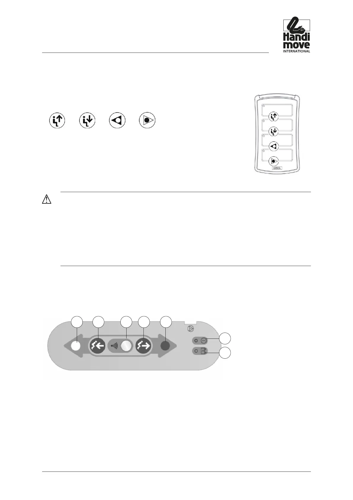
6.2. The infrared handcontrol for 2805 IR and 2815 L IR
The infrared handcontrol (I) has 4 buttons, UP, DOWN, LEFT and RIGHT, which are
indicated with the appropriate arrows.
LIFTING MOTOR LATERAL MOTOR
UP DOWN LEFT RIGHT
The .LEFT. and .RIGHT. buttons are not relevant for the 2805 IR model, as this
model does not have the lateral motor.
Remove the three 1,5 V AAA batteries from the infrared handcontrol when you are
not using the motor for an extended period of time.
CAUTION!
make sUre that the infrared handcontrol does not/cannot fall into the Water.
the ir handcontrol has a bUilt-in indicator to Warn yoU of loW battery voltage. yoU
Will hear a soUnd alert With one long beeP and three short beePs Played tWice. this
occUrs aboUt 10 seconds after the transmitter Was last Used. rePlace the batteries as
soon as Possible.
6.3. The Control Panel (for emergency operation)
The Control Panel (H) contains:
1 2 3 4 5
6
7
1. Emergency operation (left) (only for models with lateral motor)
2. Emergency operation (descend)
3. Infrared signal receiver (only for 2805 IR and 2810 L IR)
4. Emergency operation (lifting up)
5. Emergency operation (right) (only for models with lateral motor)
6. On/off LED
Emergency stop switch activated = LED is not lit
Emergency stop switch not activated = LED is green