Do you have a question about the H&S H D 7+4 FEEDER BOX and is the answer not in the manual?
| Brand | H&S |
|---|---|
| Model | H D 7+4 FEEDER BOX |
| Category | Farm Equipment |
| Language | English |
Checklist for pre-delivery inspection by the dealer to ensure proper setup and operation.
Checklist for passing important information to the customer during equipment delivery.
Introduces the 'Be Alert' concept and its significance for operator safety.
Explains the safety-alert symbol and the importance of following precautions.
Explains DANGER, WARNING, and CAUTION signal words used in the manual.
Emphasizes reading and following all safety messages and recommended procedures.
Stresses the importance of a properly functioning emergency stop system for safety.
Warns operators to stay clear of beaters and cross conveyors when the power is on.
Advises maintaining safe distance from electric power lines to prevent shock.
Outlines safety precautions required before entering the forage box.
Alerts about the dangers of high-pressure oil leaks and necessary precautions.
Instructs not to operate if safety decals are exposed and to replace shields.
Advises closing access doors before operating due to exposed rotating parts.
Provides guidelines to prevent injury, including reading the manual and keeping clear of moving parts.
Cautions to stop the machine and tractor before adjusting or greasing.
Warns against removing shields and highlights danger from moving parts inside.
A direct warning to keep children away from the equipment at all times.
Alerts to stay clear of specific areas identified with moving parts.
Covers essential safety rules for operating the feeder box, including general precautions and hazards.
Details procedures for using the emergency stop and clearing machine clogs safely.
Focuses on specific safety measures related to beaters and conveyors during operation.
Outlines maintenance steps for the emergency stop system to ensure proper function.
Provides instructions on how to reset the emergency stop mechanism after activation.
Explains the operation of the emergency stop system using cables and panels.
Repeats the warning about hydraulic leaks and associated hazards.
Informs that guards may be removed in photos for clarity, stressing they must be in place during operation.
Details the thorough checks required before the first operation of the unit.
Explains the use of SMV emblems and reflective tape for highway transport safety.
Provides instructions on how to adjust the main feeder apron chain tension.
Details the process for adjusting the cross conveyor chain tension.
Describes the function of the plastic guard protecting against the bottom beater.
Explains the purpose and replacement procedure for shear bolts in the cross conveyor.
Provides initial lubrication guidance for gear boxes and drive chains.
Lists the locations of all 21 grease fittings on the feeder box.
Advises on the frequency of greasing during normal use and storage.
Stresses the importance of decals for safety and how to order replacements.
Provides a comprehensive list of all decals with their part numbers and descriptions.
Lists crucial safety reminders for operating the feeder box in the field.
Step-by-step instructions for initiating the unloading process.
Procedures for safely unhooking and preparing the feeder box after unloading.
Explains the wiring color code and illustrates the lighting assembly diagram.
Lists the parts and their descriptions for the lighting assembly.
Provides instructions on how to order replacement parts, including necessary information.
States the company's policy on making improvements and changes to products.
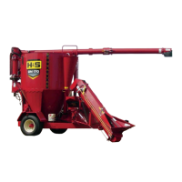
Illustrates the various components that make up the housing of the feeder box.
Lists and describes each part of the feeder box housing.
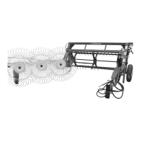
Depicts the components of the beaters and main apron drive assembly.
Lists and describes all parts associated with the beaters and main apron drive.
Illustrates the components of the cross apron and its drive assembly.
Lists and describes each part of the cross apron and drive assembly.
Shows the various shields and guards used on the feeder box.
Lists and describes the individual parts of the shields and guards.
Illustrates the internal components of the bevel gearbox.
Lists and describes all parts that comprise the bevel gearbox.
Depicts the components of the worm gearbox assembly.
Lists and describes each part of the worm gearbox.
Shows an exploded view of the feeder box and its various components.
Provides a detailed list of parts for the feeder box and its components.
Illustrates the hydraulic system with a two-hose configuration.
Lists and describes all parts of the hydraulic system.
Depicts the internal components of the hydraulic cylinder.
Lists and describes each part of the hydraulic cylinder.
Shows the components of the elevator extension assembly.
Lists and describes all parts related to the elevator extension.
Illustrates the components of the control box assembly.
Lists and describes each part of the control box assembly.
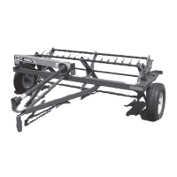
Depicts the components of the feeder box's running gear.
Lists and describes all parts of the running gear assembly.
Details the power source and hydraulic system requirements for the feeder box.
Lists specifications related to speeds, dimensions, and capacity.
Covers specifications for tires, controls, and construction materials.