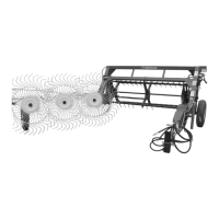
TEDDER REEL SPEED
The tedder reel is driven hydraulically to allow the opera-
tor to better coordinate the speed of the reel with the
ground speed and teeth angle. Adjust reel speed with
g
round speed so when tedder reel passes over the
windrow it gently lifts and fluffs the hay, but does not
t
hrow hay into the air. To adjust reel speed, shut off the
tractor and disengage the tractor hydraulics. Move selec-
tor lever (A) located on speed control valve to the desired
speed. Correct reel speed will vary depending on hay
conditions, tooth angle, and ground speed.
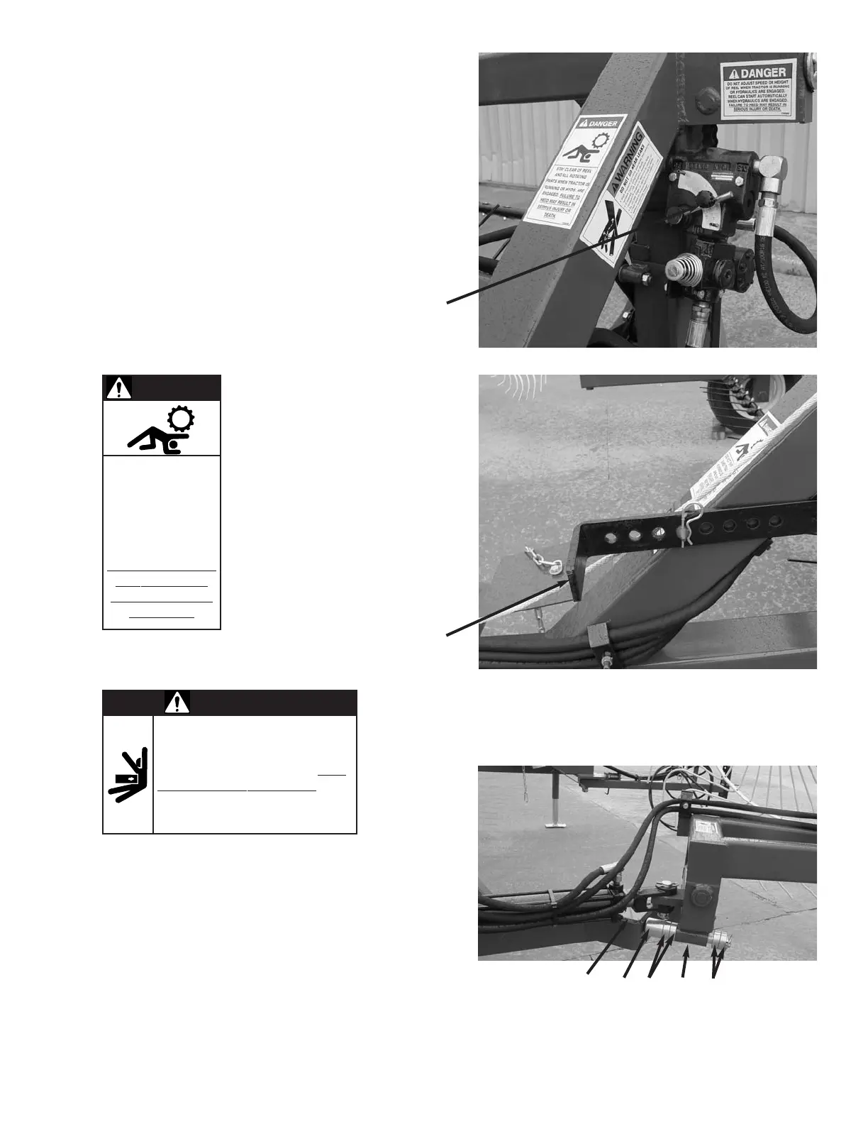
TEDDER TEETH
The aggressiveness of the tedder
teeth to gently lift and fluff various
types of hay can be regulated by
moving the adjustment lever (A)
located on the left hand side of the
Haymachine II. There are eight (8)
different settings. Moving the lever
forward will make the teeth move
aggressive and lift hay higher, while
moving the lever rearward will lessen
this effect. After changing the angle
of the teeth, recheck the height
adjustment of the tedder reel to
assure proper and most efficient
operation of the Haymachine II.
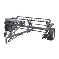
RAKE BEAM
The angle of the main rake beam can be changed to accommodate dif
-
ferent windrow widths and crop conditions. The three rake wheels will
turn up to approximately a four and a half foot windrow depending on the
angle of the rake beam. To change the angle of rake beam, increase or
decrease the
number of
spacers (A) on
adjustment
shaft (B)
between adjustment stop (C)
and adjustment shaft hold
-
er (D). Increasing the number of spacers will lessen the
angle of rake wheels and decrease raking width. This will
also make the rake wheels more aggressive when raking
hay that has been rained on or is very heavy and green.
To adjust angle of the rake beam, partially close rake
bream. Remove clip pin from adjustment shaft (B) and
remove shaft from holder bracket (D). Place desired num-
ber of spacers (A) on adjustment shaft and insert shaft
back into holder on rake beam from cylinder side of hold
-
er. Place remaining spacers on shaft and install clip pin.
-11-
DO NOT SHIFT
LEVER WHEN
TRACTOR IS RUN-
NING OR HYDS.
ARE ENGAGED.
F
AILURE TO HEED
MAY RESULT IN
SERIOUS INJURY
OR DEATH.
STAY CLEAR OF RAKE WHEN
OPENING OR CLOSING. FAILURE
TO HEED MAY RESULT IN PER
-
SONAL INJURY OR DEATH. KEEP
CLOTHING,
YOURSELF
AND OTHERS WELL CLEAR.
DANGER
DANGER
A
A
C B
AD A